Altera Stratix IV GX FPGA Development Board User Manual
Page 29
Chapter 2: Board Components
2–21
Configuration, Status, and Setup Elements
August 2012
Altera Corporation
Stratix IV GX FPGA Development Board
Reference Manual
lists the rotary switch component reference and manufacturing
information.
3
S4VCCIO_INT
2.5
VCCPD
I/O pre-drivers
VCCPGM
Configuration I/O
VCC_CLKIN
V
cc
clock input pins
4
S4VCCH_GXB
1.4
VCCH_GXB
XCVR clock buffers
5
S4VCCAUX
2.5
VCCAUX
Programmable power tech auxiliary
VCCA_PLL
PLL analog
6
S4VCCPT
1.5
VCCPT
Programmable power tech
7
S4VCCD_PLL
0.90
VCCD_PLL
PLL digital
8
S4VCCA_GXB
3.0
VCCA_GXB
XCVR analog TX/RX driver (mA only)
9
S4VCCIO_B5
2.5
VCCIO_B5
Bank 5 I/O power (HSMC port A)
A
S4VCCIO_B6
2.5
VCCIO_B6
Bank 6 I/O power (HSMC port B)
B
S4VCCIO_B1B2
2.5
VCCIO_B1
Bank 1 I/O power (FSM bus)
VCCIO_B2
Bank 2 I/O power (FSM bus)
C
S4VCCIO_B3A
1.8
VCCIO_B3A
Bank 3A I/O power (HDMI)
D
S4VCCIO_B3B4
1.5
VCCIO_B3
Bank 3 I/O power (DDR3BOT)
VCCIO_B4
Bank 4 I/O power (DDR3BOT)
E
S4VCC_GXB
1.1
VCCR
XCVR analog receive
VCCT
XCVR analog transmit
VCCL_GXB
XCVR clock distribution
F
12 V
12
—
All 12 V power
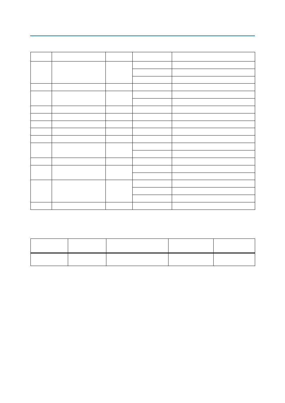
Table 2–18. Power Rail Measurements Based on the Rotary Switch Position (Part 2 of 2)
Switch
Schematic Signal Name
Voltage (V)
Device Pin
Description
Table 2–19. Rotary Switch Component Reference and Manufacturing Information
Board Reference
Description
Manufacturer
Manufacturer
Part Number
Manufacturer
Website
SW2
16-position rotary
switch
Grayhill Corporation
94HCB16WT