Setup elements, Board settings dip switch, Setup elements –18 – Altera Stratix IV GX FPGA Development Board User Manual
Page 26: Board settings dip switch –18
2–18
Chapter 2: Board Components
Configuration, Status, and Setup Elements
Stratix IV GX FPGA Development Board
August 2012
Altera Corporation
Reference Manual
Setup Elements
The development board includes several different kinds of setup elements. This
section describes the following setup elements:
■
Board settings DIP switch
■
JTAG control DIP switch
■
PCI Express control DIP switch
■
Reset configuration push button
■
Rotary switch
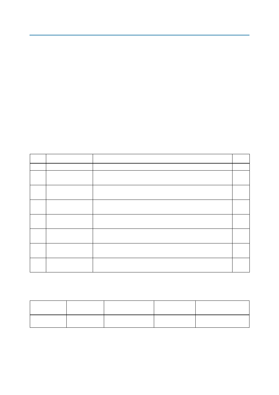
Board Settings DIP Switch
The board settings DIP switch controls various features specific to the board and the
MAX
II CPLD EPM2210 System Controller logic design.
lists the switch
controls and descriptions.
lists the board settings DIP switch component reference and
manufacturing information.
Table 2–11. Board Settings DIP Switch Controls
Switch Schematic Signal Name
Description
Default
1
MAX_DIP
Reserved
OFF
2
USB_DISABLEn
ON : Embedded USB-Blaster disabled
OFF : Embedded USB-Blaster enabled
OFF
3
LCD_PWRMON
ON : LCD driven from the Max II EPM2210 System Controller (power monitor)
OFF : LCD driven from the FPGA (no power monitor)
ON
4
FAN_FORCE_ON
ON : Fan forced ON
OFF : Fan speed controlled by the MAX1619 device
OFF
5
CLK_SEL
ON : 100 MHz oscillator input select
OFF : SMA input select
ON
6
CLK_ENABLE
ON : On-Board oscillator enabled
OFF : On-Board oscillator disabled
ON
7
S4VCCH_SEL
ON : 1.4 V (default)
OFF : Reserved
ON
8
S4VCCA_SEL
ON : 3.3 V (default)
OFF : 2.5 V
ON
Table 2–12. Board Settings DIP Switch Component Reference and Manufacturing Information
Board Reference
Description
Manufacturer
Manufacturer
Part Number
Manufacturer Website
SW4
Eight-position slide
DIP switch
C & K Components
TDA08H0SB1