Setup elements, Board settings dip switch, Setup elements –16 – Altera Cyclone V GT FPGA Development Board User Manual
Page 24: Board settings dip switch –16
2–16
Chapter 2: Board Components
Setup Elements
Cyclone V GT FPGA Development Board
September 2014
Altera Corporation
Reference Manual
Setup Elements
The development board includes several different kinds of setup elements. This
section describes the following setup elements:
■
Board settings DIP switch
■
JTAG chain control or PCI Express control DIP switch
■
FPGA configuration mode DIP switch
■
CPU reset push button
■
MAX V reset push button
■
Program configuration push button
■
Program select push button
f
For more information about the default settings of the DIP switches, refer to the
.
Board Settings DIP Switch
The board settings DIP switch (SW4) controls various features specific to the board
and the MAX V CPLD 5M2210 System Controller logic design.
lists the
switch controls and descriptions.
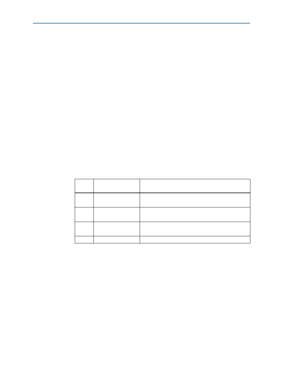
Table 2–8. Board Settings DIP Switch Controls
Switch
Position
Schematic Signal Name
Description
1
CLK_SEL
ON: Select programmable oscillator clock
OFF: Select SMA input clock
2
CLK_ENABLE
ON: Disable on-board oscillator
OFF: Enable on-board oscillator
3
FACTORY_USER
ON: Load the factory design at power up
OFF: Load the user design from flash at power up
4
ASSP_MODE
Not used