Nextrow guidelines, Azimuth degree, Nextrow guidelines azimuth degree – TeeJet Matrix Pro 840GS User Manual
Page 49: End row, Turn now, Mark a, Enter azimuth (deg)
43
98-05273-ENUS R4
HOME
OVER
VIE
W
SE
TUP
IMPLEMENT
FULL SCREEN
GPS
INTR
ODUC
TION
GUID
ANCE
DR
OPLE
T MONIT
OR
NextRow Guidelines
NextRow Guidance indicates where the next row is located
based on the programd guidance width and provides guidance
at user marked row ends to the next adjacent row. When the operator
signals the end of the row, a Straight AB line will be established in the
current row and guidance is provided to the NextRow. When the
vehicle is in the NextRow, guidance is turned off.
NOTE: Offset to NextRow will be calculated using the guidance
width, which is established in Unit Setup under
Implement Setup.
To activate NextRow guidelines:
1. Press NAVIGATION AND GUIDANCE OPTIONS tab
to
display navigation options.
2. At the end of a row (while driving a straight line)
press MARK B icon
B
.
◄The end of the row will be marked with a green point .
3. Turn toward the next row.
4. Based on that direction turned, guidance will be provided for the
next adjacent row.
◄When the vehicle is in the row, the guideline is removed
5. Repeat at the end of the next row.
NOTE: The NextRow Guidance feature does not support
skipping rows.
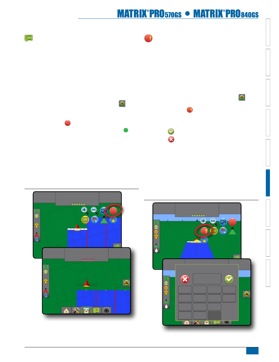
Figure 6-21: Mark End of Row
3:22 PM
7.2
mph
End Row
B
3:28 PM
7.2
mph
Turn Now
Azimuth degree
A
An azimuth is defined as a horizontal angle measured
clockwise from a north base line. When using an
azimuth, the point from which the azimuth originates is the
center of an imaginary circle. This circle is divided into 360°.
North = 0, East = 90, South = 180, West = 270.
An azimuth degree can be entered to determine the exact
location of the vehicle. When a navigation mode is selected, the
azimuth degree can be entered.
To establish an Azimuth Degree guideline:
1. Press NAVIGATION AND GUIDANCE OPTIONS tab
to
display navigation options.
2. Press AZIMUTH icon
A
to enter azimuth degree.
3. Use the entry screen to establish the Azimuth degree.
4. Press:
►Accept
to save the settings
►Cancel
to leave the keypad without saving
5. “Would you like to name this guideline?”
Press:
►Yes – to enter a name and save the guideline
►No – to automatically generate a name
The console will begin providing navigation information.
To establish additional azimuth guidelines, follow the same steps as
the initial azimuth guideline.
Figure 6-22: Azimuth Guidance
1:12 PM
7.2
mph
Mark A
A
A
1:14 PM
7.2
mph
> 0.0 <
enter azimuth (deg)
1
2
3
0
Clear
4
5
6
<--
7
8
9
0
.
+/-