Wiring the digital inputs / outputs (ge-dsh-73) – Interlogix GE-DSH-73 Series User Manual User Manual
Page 32
Chapter 2: Installation
28
GE-DSH-73/DSH-82 and DSH-82-PoE User Manual
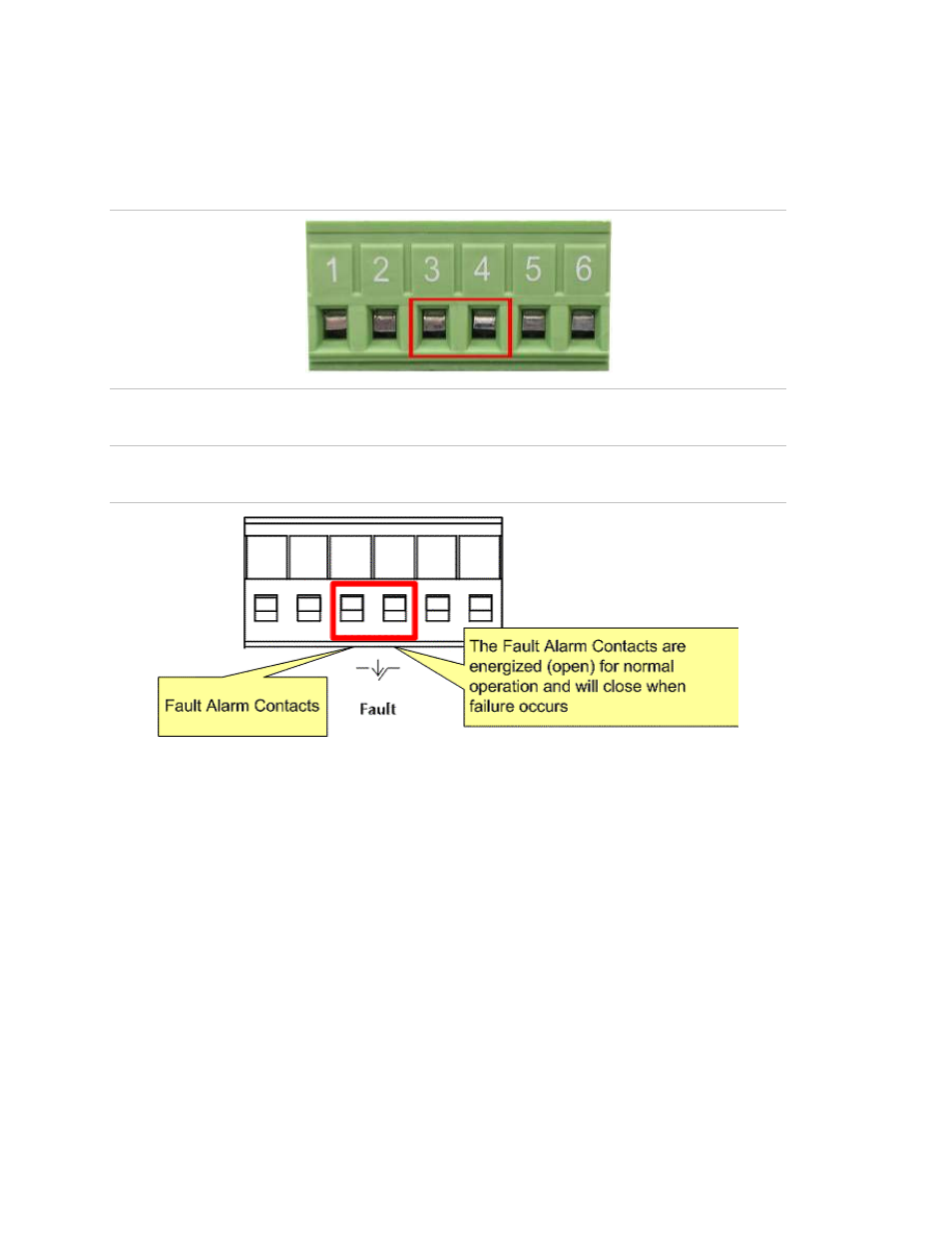
forms an open circuit. The following illustration shows an application example for
wiring the fault alarm contacts.
Figure 2-16
:
6-Pin Terminal Block Fault Alarm contact
NOTE:
The wire gauge for the terminal block should be in the range between 12 ~ 24
AWG.
Figure 2-17
:
Power Fault Alarm trigger description
Wiring the Digital Inputs / Outputs (GE-DSH-73)
There is another terminal block comprising two sets of digital input/output contacts
on the topside of GE-DSH-73. Please refer to the Digital Input/Output section for how
to configure Digital Input/Output. The following illustration shows the pin assignment
of the DIDO connector. Please note do not connect DO0/DO1 to the external device
using power higher than 40V/200mA.