Wiring the fault alarm contact – Interlogix GE-DSH-73 Series User Manual User Manual
Page 31
Chapter 2: Installation
GE-DSH-73/DSH-82 and DSH-82-PoE User Manual
27
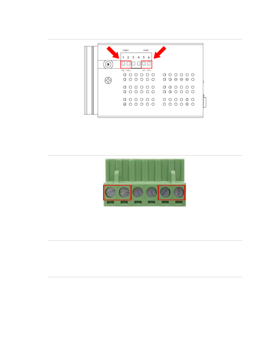
Figure 2-14
:
Wiring the redundant power inputs
3. Tighten the wire-clamp screws to prevent the wires from coming loose.
Figure 2-15
:
Wiring the redundant power inputs
1 2 3 4 5 6
Power 2
Power 1
- + - +
NOTE:
The wire gauge for the terminal block should be in the range between 12 ~ 24
AWG.
For the GE-DSH-82-PoE, A 48VDC, 3A power input is required for full PoE load on the
PoE. Please connect an external power source to the terminal block that can supply
steady power at 48VDC.
Wiring the Fault Alarm Contact
The fault alarm contacts are in the middle of the terminal block connector as the
picture shows below. Inserting the wires, the Industrial Switch will detect the fault
status of the power failure, or port link failure (available for managed model) and then