Wiring the power inputs – Interlogix GE-DSH-73 Series User Manual User Manual
Page 30
Chapter 2: Installation
26
GE-DSH-73/DSH-82 and DSH-82-PoE User Manual
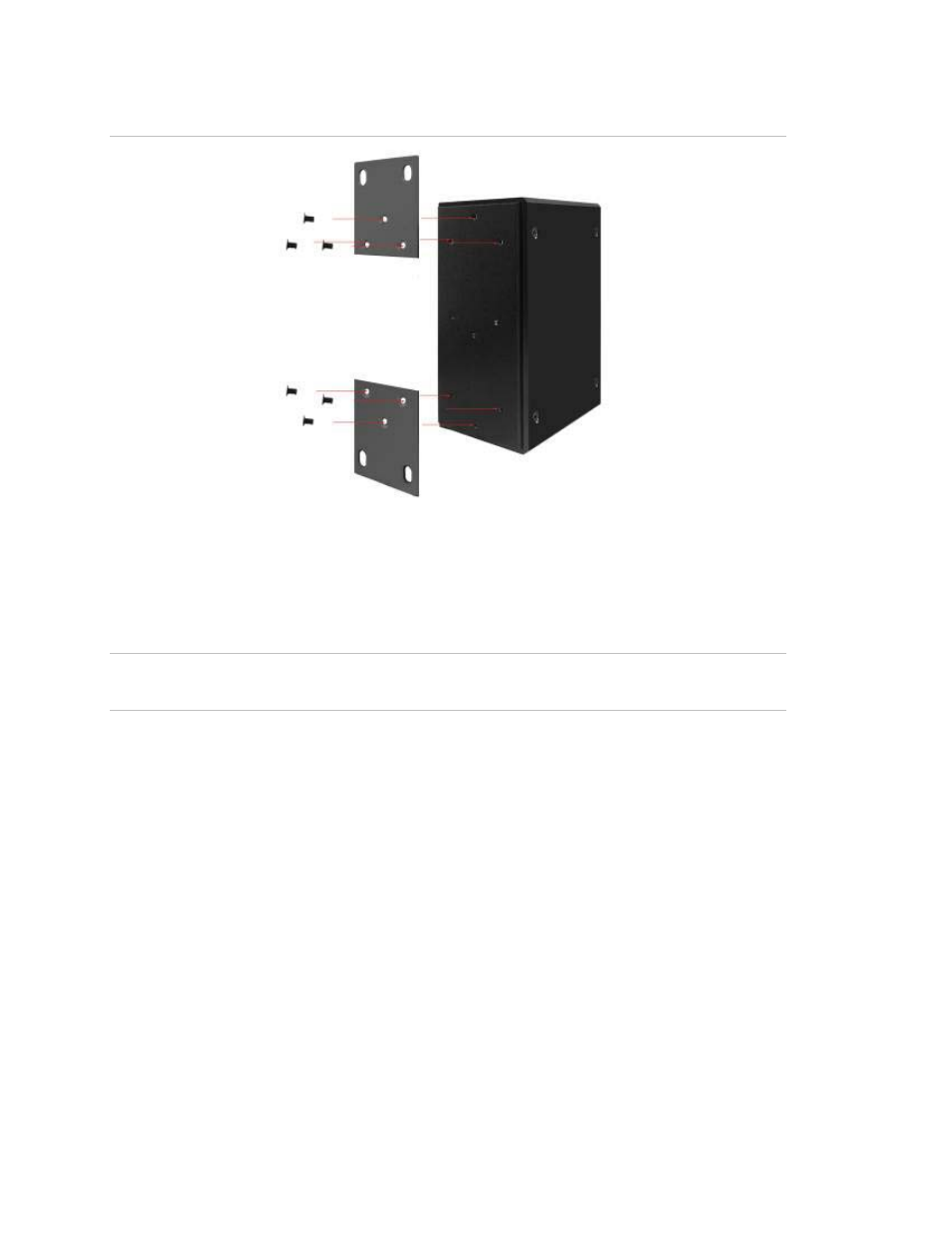
Figure 2-13
:
Wall mounting
Wiring the Power Inputs
The 6-contact terminal block connector on the top panel of GE-DSH-82-PoE is used
for two DC redundant power inputs.
NOTE: This product is intended to be supplied by a UL Listed Direct Plug-In Power Unit
marked "Class 2" or "LPS" and output rated 48 VDC, 380 mA minimum.
Please follow the steps below to insert the power wire.
1. Insert the positive / negative DC power wires into the contacts 1 and 2 for POWER
2, or 5 and 6 for POWER 1.
This manual is related to the following products:
See also other documents in the category Interlogix Accessories communication:
- 600-1053-4 (12 pages)
- NX-590NE (38 pages)
- NX-591NE-GSM (16 pages)
- NX-592E (13 pages)
- Simon XT CDMA Module V4 (9 pages)
- Simon XT GSM Module V4 (10 pages)
- NX-548E (12 pages)
- NX-540E (32 pages)
- D1000 Series (10 pages)
- D1300 Series (11 pages)
- D1315 Series (10 pages)
- D1810 Series (8 pages)
- D2100 Series (10 pages)
- D2300CPS Series (10 pages)
- D7100 Series (8 pages)
- D7400 Series (10 pages)
- D7400RSH Series (10 pages)
- DE7100 Series (9 pages)
- DE7200M Series (8 pages)
- DE7300 Series (9 pages)
- DECT3000 Series (8 pages)
- DED2500 Series (9 pages)
- DT3000 Series (6 pages)
- D1200 Series (8 pages)
- D19100SHR Series (16 pages)
- D9100 Series (12 pages)
- MC250-4T/1CXT (25 pages)
- MC251-4P/1CXT (28 pages)
- MC250-4T Series (23 pages)
- MC251-4P/1S (27 pages)
- MC350-4T-2S (32 pages)
- MC352-4P-2S (31 pages)
- MCR200-1T/1CX (25 pages)
- MCR200-1T-1TW (23 pages)
- MC250-1T/1S (24 pages)
- MCR205-1T/1S User Manual (62 pages)
- MCR205-1T/1S Installation Guide (11 pages)
- MC201-1P/1FS (20 pages)
- MC355-1T/1S Installation Guide (13 pages)
- MC350-1T-2S (29 pages)
- MC352-1P/1S (29 pages)
- MC355-1T/1S User Manual (64 pages)
- MCR300-1T/1S (20 pages)
- MCR300-1T-2S (17 pages)
- MCR-R15 (14 pages)