Wire synchronization system, Wire synchronization system -12, Transmitter: 7-core cable, receiver: 7-core cable – KEYENCE GL-RHG Series User Manual
Page 82: Reference, 1) pnp output cable (2) npn output cable, 5 examples of wiring
4-5
Examples of Wiring
4-12
GL-RHG-M-NO4-E
Wirin
g
4
Wire synchronization system
Reference
Different core number cables can be used for the transmitter and receiver at the same time.
For example, using the 11-core cable for the transmitter and 7-core cable for the receiver.
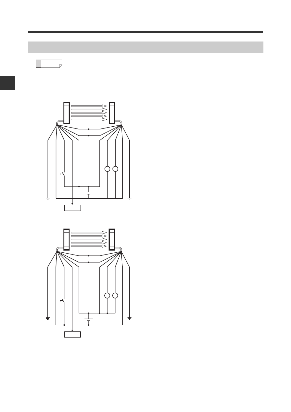
Transmitter: 7-core cable, Receiver: 7-core cable
(1) PNP output cable
(2) NPN output cable
R1
R2
PLC
(FE) Gre
y
(0
V)
B
lu
e
(W
ait in
pu
t)) Wh
ite
(E
rro
r o
utp
ut) B
lac
k
(+
24 V)
B
ro
w
n
(+
24 V)
B
ro
w
n
(OSS
D1
) B
lac
k
(OSS
D2
) Wh
ite
(0
V)
B
lu
e
(FE) Gre
y
Orange (Synchronization 1)
S2
Tra
nsm
itter
Re
ce
iv
er
Orange/Black
(Synchronization 2)
R1
R2
PLC
(FE
) Gr
ey
(0
V)
B
lu
e
(W
ai
t in
pu
t)
) Wh
ite
(E
rro
r o
utp
ut) B
lac
k
(+
24
V)
Br
ow
n
S2
(+
24
V)
Br
ow
n
(OSS
D1
) B
lac
k
(OSS
D2
) Wh
ite
(0
V)
B
lu
e
(FE
) Gr
ey
Orange (Synchronization 1)
Orange/Black
(Synchronization 2)
Tran
sm
itter
Re
ce
iv
er