5 examples of wiring – KEYENCE GL-RHG Series User Manual
Page 81
4-5
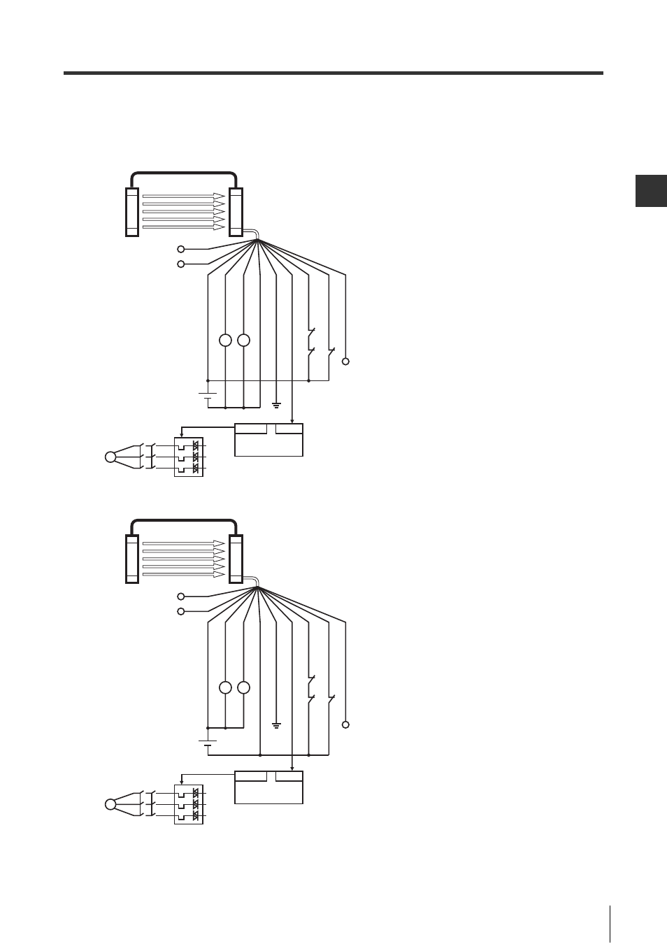
Examples of Wiring
4-11
GL-RHG-M-NO4-E
Wirin
g
4
Transmitter: Series connection cable, Receiver: 11-core cable
EDM input used
(1) PNP output cable
(2) NPN output cable
PLC
M
K2
K1
OUT
IN
(+
24
V)
B
ro
w
n
(OS
S
D1
) B
lac
k
(OSS
D2
) Wh
ite
(0
V)
B
lu
e
(FE) Gre
y
(A
UX o
utp
ut) Re
d
(E
DM
in
pu
t) Re
d/B
la
ck
(Re
set in
pu
t)
Y
ello
w
(N
ot
in
u
se)
Pi
nk
K1
K2
S1
*1
K3
K1 K2
Tra
ns
m
itter
Re
ceiv
er
Orange (Not in use)
Orange/Black (Not in use)
*1
When not using the reset input to reset from an error condi-
tion, insulate the yellow wire of the receiver.
PLC
M
K2
K1
OUT
IN
(+
24
V)
Br
ow
n
(O
SSD
1)
B
lac
k
(O
SSD2
) Wh
ite
(0
V)
Blu
e
(F
E
) Gr
ey
(A
UX
ou
tpu
t) Red
(E
D
M
in
pu
t)
Re
d/
Bl
ac
k
(R
es
et in
pu
t)
Y
ell
ow
(N
ot
in
u
se)
Pin
k
K1
K2
S1
*1
K3
K1 K2
Tr
an
sm
itte
r
Re
ce
iv
er
Orange (Not in use)
Orange/Black (Not in use)
*1
When not using the reset input to reset from an error condi-
tion, insulate the yellow wire of the receiver.
- GL-R Series (12 pages)
- GL-RHG Series (12 pages)
- GL-T11R (8 pages)
- SL-U2 (2 pages)
- SL-C Series (1 page)
- SL-V Series (10 pages)
- SL-V Series (168 pages)
- SL-C Series (54 pages)
- SL-M Series (8 pages)
- SL-T11R (6 pages)
- SL-VH1S (60 pages)
- SL-VHS Series (10 pages)
- SL-CHG Series (54 pages)
- SL-CHS Series (54 pages)
- SL-R11 (42 pages)
- SL-R11E (46 pages)
- SL-R12EX (76 pages)
- SJ Series (1 page)
- SJ-H Series (14 pages)
- SJ-HA Series (12 pages)
- SJ-HS/HW/HM (2 pages)
- SJ-F2000 Series (4 pages)
- SJ-F031 (10 pages)
- SJ-F300 Series (14 pages)
- SJ-F100W/100/010 (56 pages)
- SJ-M400 (14 pages)
- SJ-M100 (16 pages)
- SJ-M201 (16 pages)
- SJ-M300 (14 pages)
- CA-CNX10U (4 pages)
- CA-DC21E (2 pages)
- CA-HX048C (2 pages)
- CA-HX200C (2 pages)
- CA-HX500C (2 pages)
- XG Series (22 pages)
- XG VisionTerminal (58 pages)
- XG-8000 Series (12 pages)
- XG-8700T (12 pages)
- XG-7000 Series (8 pages)
- CA-H2100C (2 pages)
- CA-U4 (2 pages)
- CV-X Series (20 pages)
- CV-X Series (24 pages)
- CV-X Series (16 pages)