Wiring the muting inputs, Time chart, Point – KEYENCE GL-RHG Series User Manual
Page 43
2-5
Temporary Suspension of Safety Function
2-19
GL-RHG-M-NO2-E
Fu
nct
ion
s and
Feat
ures
2
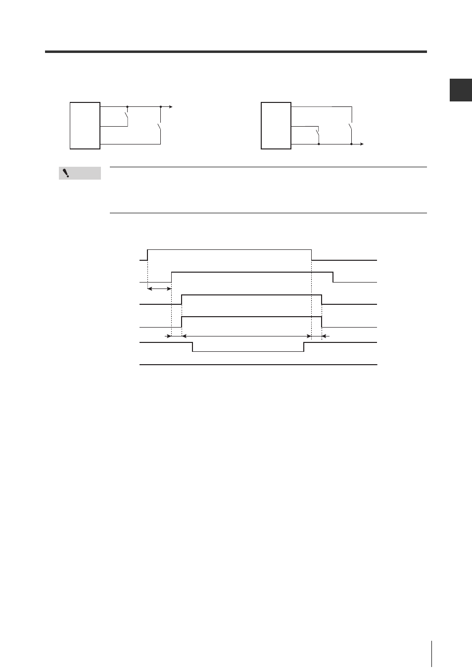
Wiring the muting inputs
Point
The output type of the switch or sensor used as the muting device must be the same as the
cable used.
Example: PNP output if PNP cable is used, or NPN output if NPN cable is used.
Also, the muting device must be able to handle a 3 mA current load.
Time chart
When using the PNP output cable
Brown
Pink
(Muting input 1)
GL-RHG
Transmitter
+24 V
Switch A1
Switch A2
Red/Black
(Muting input 2)
When using the NPN output cable
Blue
Pink
(Muting input 1)
GL-RHG
Transmitter
0V
Switch A2
Switch A1
(Muting input 2)
Red/Black
Sensor A1
Sensor A2
Muting lamp
OSSD
Not muted condition
Within approx. 5 min.
Within 0.04
to 3 s
90 ms max.
90 ms max.
GL-RHG
ON
OFF
Clear
Blocked
Light ON
Light OFF
ON
OFF
ON
OFF
Muted condition
- GL-R Series (12 pages)
- GL-RHG Series (12 pages)
- GL-T11R (8 pages)
- SL-U2 (2 pages)
- SL-V Series (168 pages)
- SL-C Series (1 page)
- SL-V Series (10 pages)
- SL-C Series (54 pages)
- SL-M Series (8 pages)
- SL-T11R (6 pages)
- SL-VH1S (60 pages)
- SL-VHS Series (10 pages)
- SL-CHG Series (54 pages)
- SL-CHS Series (54 pages)
- SL-R11 (42 pages)
- SL-R11E (46 pages)
- SL-R12EX (76 pages)
- SJ Series (1 page)
- SJ-H Series (14 pages)
- SJ-HA Series (12 pages)
- SJ-HS/HW/HM (2 pages)
- SJ-F2000 Series (4 pages)
- SJ-F031 (10 pages)
- SJ-F300 Series (14 pages)
- SJ-F100W/100/010 (56 pages)
- SJ-M400 (14 pages)
- SJ-M100 (16 pages)
- SJ-M201 (16 pages)
- SJ-M300 (14 pages)
- CA-CNX10U (4 pages)
- CA-DC21E (2 pages)
- CA-HX048C (2 pages)
- CA-HX200C (2 pages)
- CA-HX500C (2 pages)
- XG Series (22 pages)
- XG VisionTerminal (58 pages)
- XG-8000 Series (12 pages)
- XG-8700T (12 pages)
- XG-7000 Series (8 pages)
- CA-H2100C (2 pages)
- CA-U4 (2 pages)
- CV-X Series (24 pages)
- CV-X Series (16 pages)
- CV-X Series (22 pages)