KEYENCE GL-RHG Series User Manual
Page 55
3-2
Safety Distances
3-7
GL-RHG-M-NO3-E
In
sta
llatio
n
to
a Mac
h
in
e
3
Example 3 :ANSI/RIA R15.06-1999
Safety distance calculation according to ANSI/RIA R15.06-1999 (in a case where the protective
zone is perpendicular to the direction of approach)
Equation: S = [K × (Ts + Tc + Tr)] + Dpf
S
: Safety distance (mm)
K
: Approach speed of the body or parts of the body into the protective zone (= 63 inch/s)
Ts
: Final stop time required when stop control is issued to machine (s)
Tc
: Maximum response time of machine's control system (s)
Tr
: Maximum response time of the GL-RHG and its interface (s)
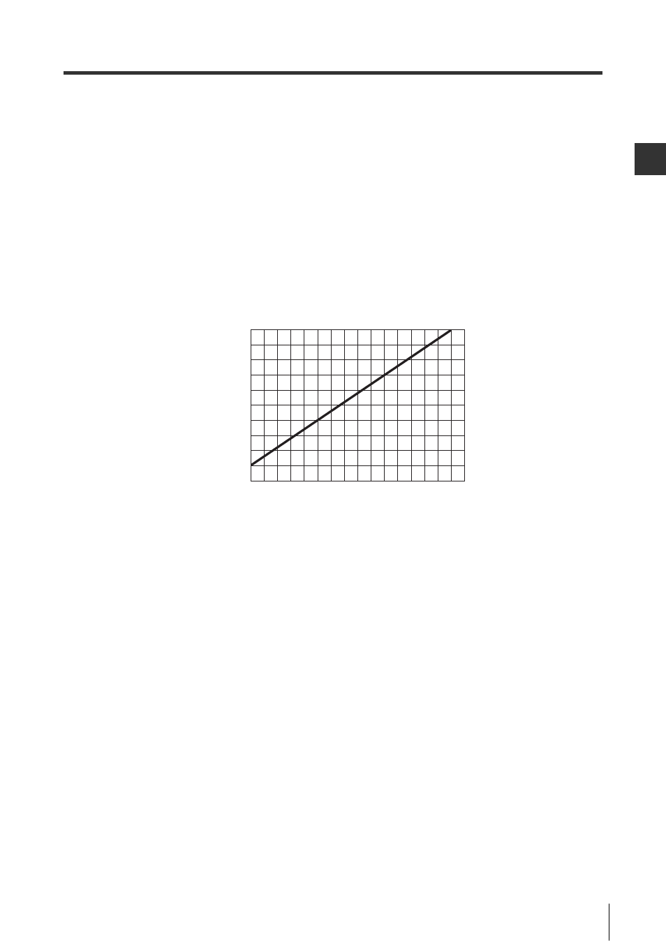
Dpf : Additional distance (mm) from the approach factor as in the following figure. This value
varies depending on the GL-RHG detection capability.
ANSI/RIA R15.06-1999 establishes K = 63 inch/s (= 1,600 mm/s) as a minimum speed.
0.0
25
(1.0)
51
(2.0)
76
(3.0)
102
(4.0)
127
(5.0)
152
(6.0)
178
(7.0)
203
(8.0)
64 (2.5)
51 (2.0)
38 (1.5)
25 (1.0)
13 (0.5)
0.0
Detection
capability:
S mm (inch)
Additional distance Dpf mm (inch)