Gas valve adjustment (48pg and pm), Puron r refrigerant – Carrier 48/50PM C16-28 User Manual
Page 91
91
Be sure unit is in normal cooling mode by checking that the RH2
solenoid coil(s) and the CRC relay are deenergized (control outputs
off). Adjust charge per the charging charts as described in the To
Use The Cooling Charging Charts, Standard Unit section. Switch
system to run in the dehumidification mode for 5 minutes.
Dehumidification mode is when the RH2 solenoid coil(s) and the
CRC relay are energized. Switch back to cooling mode to recheck
pressures and temperatures on the charging chart and adjust charge
if necessary. If charge adjustment is necessary, then repeat the steps
in this paragraph until no charge adjustment is necessary. When no
more charge adjustment is necessary after switching from
Dehumidification mode back to Cooling mode, then charge
adjustment procedure is complete. Remove jumper from the
outdoor motor speed controller.
Puron
R Refrigerant
Puron refrigerant operates at 50 to 70 percent higher pressures than
R-22. Be sure that servicing equipment and replacement
components are designed to operate with Puron refrigerant. Do not
mix with components that have been used with other refrigerants.
Puron refrigerant, as with other HFCs, is only compatible with
POE oils.
Recovery cylinder service pressure rating must be 400 psig. Puron
systems should be charged with liquid refrigerant. Use a
commercial-type metering device in the manifold hose. Manifold
sets should be 750 psig high-side and 200 psig low-side with 520
psig low-side retard. Use hoses with 750 psig service pressure
rating. Leak detectors should be designed to detect HFC
refrigerant.
Table 28 – Altitude Compensation*
48PG03−07
ELEVATION
(ft)
NATURAL GAS
ORIFICE†
PROPANE
ORIFICE†
0‐1,999
45
52
2,000
47
52
3,000
47
53
4,000
47
53
5,000
48
53
6,000
48
53
7,000
48
53
8,000
49
54
9,000
49
54
10,000
50
54
11,000
51
54
12,000
51
55
13,000
52
55
14,000
52
56
48PG08−14
ELEVATION
(ft)
NATURAL GAS
ORIFICE†
PROPANE
ORIFICE†
0‐1,999
43
50
2,000
44
51
3,000
44
51
4,000
44
51
5,000
45
51
6,000
45
52
7,000
47
52
8,000
47
52
9,000
47
53
10,000
48
53
11,000
49
53
12,000
50
54
13,000
50
54
14,000
51
55
48PG08−14
ELEVATION
(ft)
NATURAL GAS
ORIFICE†
PROPANE
ORIFICE†
0‐1,999
30
38
2,000
30
40
3,000
31
40
4,000
31
41
5,000
31
41
6,000
31
42
7,000
32
42
8,000
32
43
9,000
32
43
10,000
35
44
11,000
36
44
12,000
37
45
13,000
38
46
14,000
39
47
*As the height above sea level increases, there is less oxygen per cubic foot of air.
Therefore, heat input rate should be reduced at higher altitudes. Includes a 4%
input reduction per each 1000 ft.
†Orifices available through your Carrier dealer.
Gas Valve Adjustment (48PG and PM)
The gas valve opens and closes in response to the thermostat or
limit control.
When power is supplied to valve terminals W2 (High Fire) and C1,
the main valve opens to its preset position.
The regular factory setting is stamped on the valve body.
To adjust regulator:
1. Set unit at setting for no call for heat.
2. Turn main gas valve to OFF position.
3. Remove
1
/
8
-in. pipe plug from manifold pressure tap
connection. Install a suitable pressure-measuring device.
4. Set main gas valve to ON position.
5. Set thermostat at setting to call for heat.
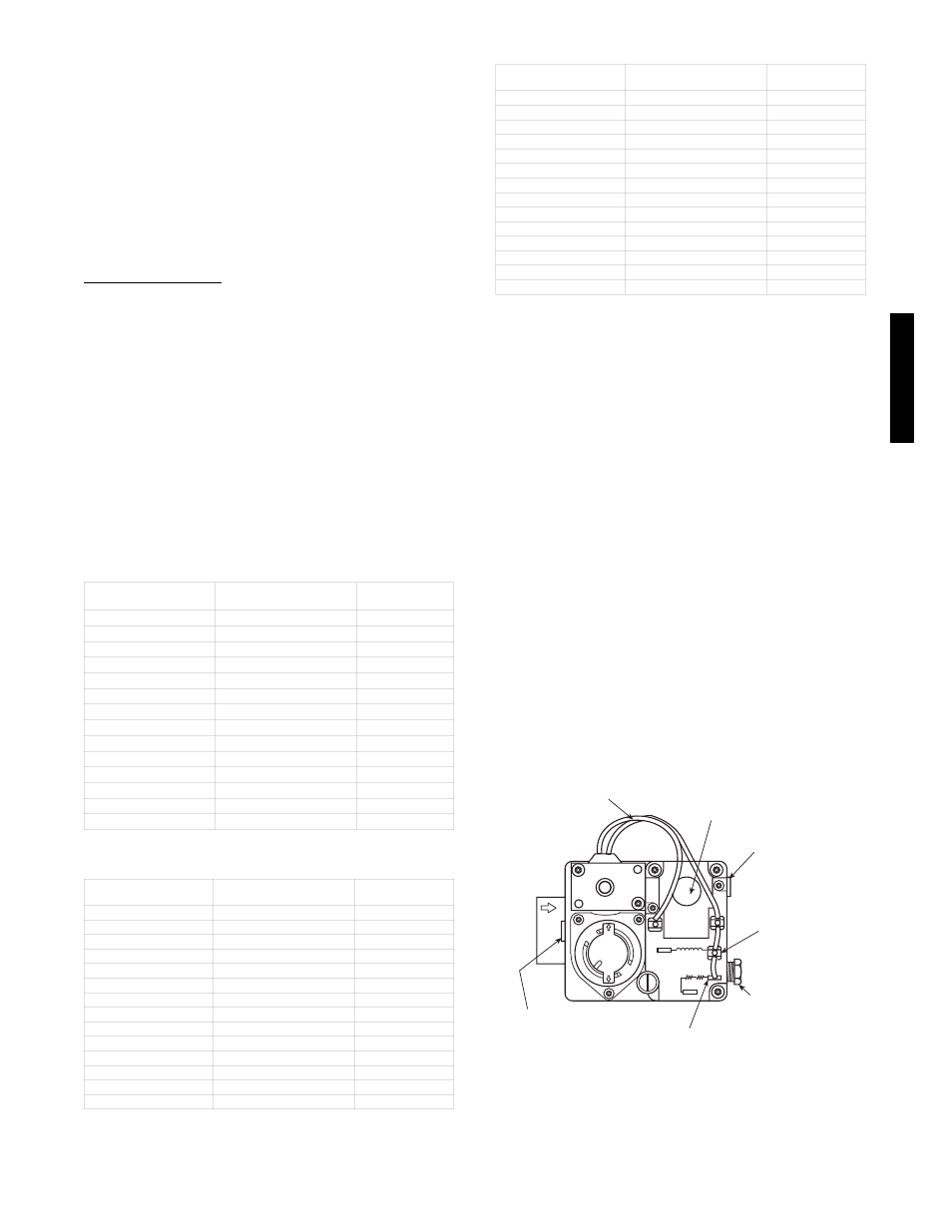
6. Remove screw cap covering regulator adjustment screw.
(See Fig. 69.)
7. Turn adjustment screw clockwise to increase pressure or
counterclockwise to decrease pressure. The setting is 3.50
in. wg on sizes 03-14 and 3.00 on size 16−28.
8. Once desired pressure is established, set unit setting for no
call for heat, turn off main gas valve, remove
pressure-measuring device, and replace
1
/
8
-in. pipe plug and
screw cap.
OFF
ON
W-1
W-2
D-1 D-2
C1
C2
PILOT
ADJ.
INLET PRESSURE TAP
(PLUGGED)
1/8 - 27 N.P.T. THDS.
2 LEADS, #18 WIRE 1/32 INSULATION,
600V. MAX., 105
°
C
REGULATOR
ADJUSTMENT SCREW
(REMOVE COVER)
OUTLET PRESSURE
TAP (PLUGGED)
1/8-27 N.P.T. THDS.
PILOT CONNECTION
FOR 1/4” O.D. TUBING
(PLUGGED)
RECEPTACLE AND
TAB COMBINATION
TERMINAL
RECEPTACLE TERMINAL
C07262
Fig. 69 −
Typical Gas Valve (20−28 Sizes Shown)
48/50PG and PM