See fig. 50, Fig. 50, Caution – Carrier 48/50PM C16-28 User Manual
Page 85: Evaporator fan service and replacement
85
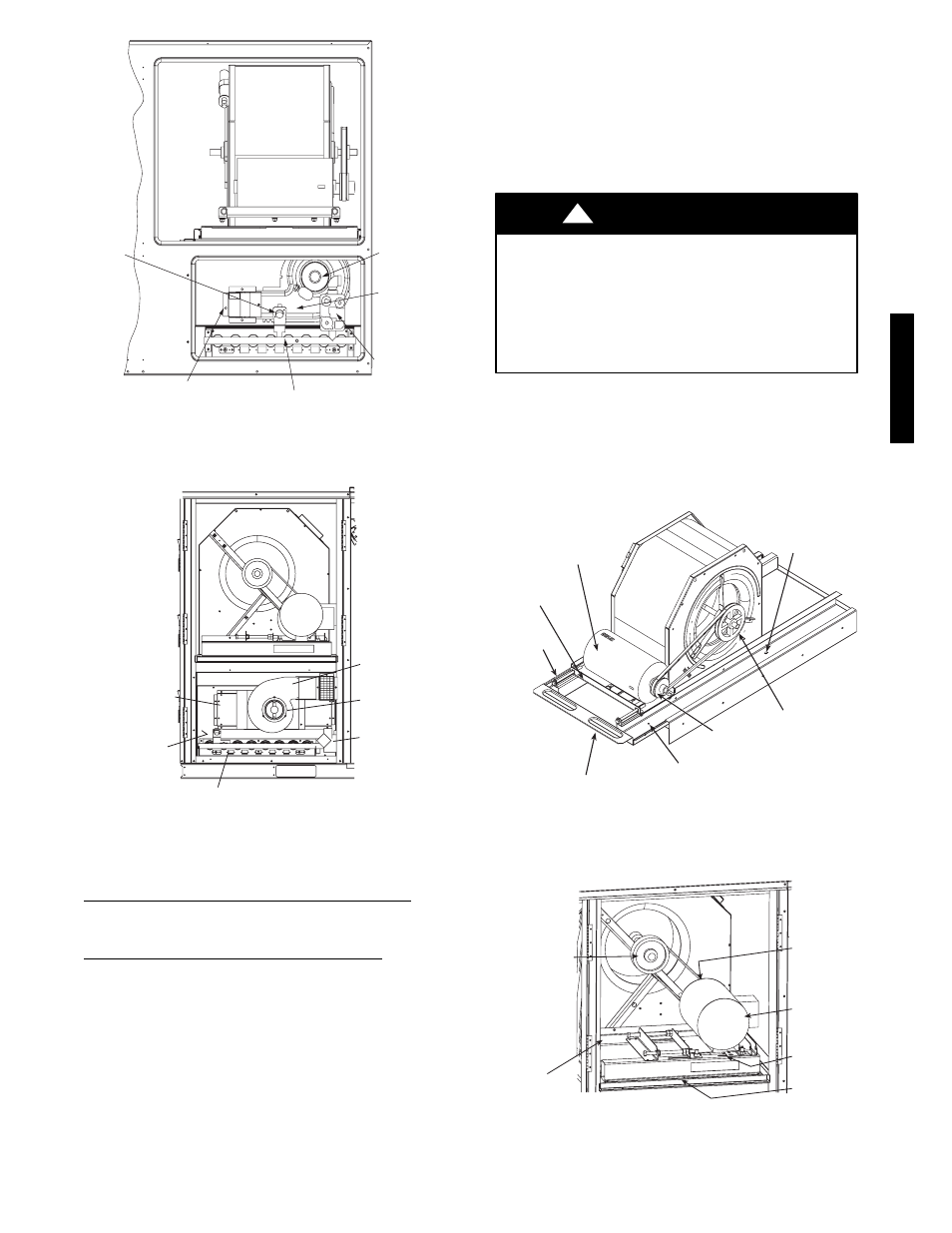
INDUCED
DRAFT
MOTOR
COMBUSTION
FAN HOUSING
MAIN GAS
VALVE
MAIN BURNER SECTION
HEAT EXCHANGER
SECTION
ROLLOUT
SWITCH
C07037
Fig. 50 −
48PG03−14 Typical Gas Heating Section
(48PG03−07 Shown)
HEAT
EXCHANGER
SECTION
IGC BOARD
(HIDDEN)
COMBUSTION
FAN HOUSING
MAIN BURNER
SECTION
INDUCED
DRAFT
MOTOR
MAIN GAS
VALVE
C07259
Fig. 51 −
48PM16−28
Typical Gas Heating Section
Condenser and Evaporator−Fan Motor Bearings
The condenser-fan and evaporator-fan motors have permanently
sealed bearings, so no field lubrication is necessary.
Economizer or Manual Outside Air Damper
If blade adjustment is required, refer to unit or accessory
installation instructions.
Evaporator Fan Service and Replacement
The units feature a slide-out fan deck for easy servicing of the
indoor-fan motor, pulleys, belt, and bearings. To service
components in this section, perform the following procedure:
1. Turn off unit power.
2. Open the fan section access door.
3. Remove two no. 10 screws at front of slide-out fan deck.
Save screws. (See Fig. 52 or 53.)
4. For 48/50PG03−14 units, disconnect the electrical wires
connected to the slide−out fan deck (supply air thermistor
and fan status switch if installed). Wires may be damaged if
not disconnected. For 48/50PM16−28 units, disconnect the
limit switch wires located on the right side of the fan deck
(48 series only). Other wires do not need to be
disconnected.
5. Fan deck can now be slid out to access serviceable
components.
UNIT DAMAGE HAZARD
Failure to follow this caution may result in damage to the
unit.
DO NOT SLIDE FAN DECK OUT PAST THE FAN
DECK STOP. If further access is required, the fan deck
must be supported. Make sure plugs and wiring are not
pinched between fan housing and unit sheet metal post.
CAUTION
!
6. To replace fan deck to operating position, slide fan deck
back into the unit. Secure with the two no. 10 screws
removed in Step 3.
7. Re-attach electrical wires.
8. Close fan section access door.
9. Restore power to unit.
MOUNTING
BASE
FAN
PULLEY
MOTOR
PULLEY
SLIDE-OUT
FAN DECK
SCREW
SCREW
(HIDDEN)
MOTOR
FAN DECK STOP
C06177
Fig. 52 −
48/50PG03−14
Evaporator−Fan Motor Adjustment
FAN
PULLEY
MOTOR
MOUNTING
BASE
MOTOR
PULLEY
(HIDDEN)
SLIDE-OUT
FAN DECK
LIMIT
SWITCH
QUICK
CONNECT
(48PM ONLY)
C08008
Fig. 53 −
48/50PM16−28
Evaporator−Fan Motor Adjustment
48/50PG and PM