Carrier 48GH User Manual
Combination heating/cooling units, Page, 5page
Attention! The text in this document has been recognized automatically. To view the original document, you can use the "Original mode".
Carrier Parkway • Syracuse NY 13221
Combination Heating/Cooling Units
MOTE TO INSTALLER: THESE INSTRUCTIONS SHOULD BE
LEFT WITH THE EQUIPMENT OWNER.
INDEX
Page
SAFETY CONSIDERATIONS ..............................
INTRODUCTION ..................................................
2
GENERAL ............................................................
INSTALLATION ................................................
2-8
Step 1 — Rig and Place Unit ..............................
• ROOFTOP INSTALLATION
• GROUND LEVEL INSTALLATION
• CLEARANCES
• CONDENSATE DISPOSAL
• VENTING
Step
2—
Make Gas Piping Connections...
5
Page
Step 3 — Make Duct Connections .....................
5
Step 4 — Make Wiring Connections ... 6-8
• HIGH-VOLTAGE CONNECTIONS
• SPECIAL PROCEDURES FOR
208-V OPERATION
• LOW-VOLTAGE CONNECTIONS
• HEAT ANTICIPATOR SETTING
.........................................................8-16
.............................. 16,17
SERVICE
.........................................................17-20
TROUBLESHOOTING CHARTS
......................21,22
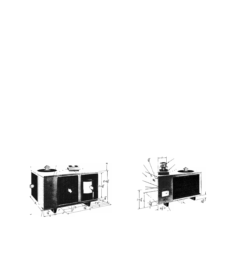
PLUGGED ACCESS HOLE
FOR REFRIGERANT . raSS-K
PRESSURE GAGE HOSES
# MPT
DRAIN CONN
*NOT ON MODELS 48GL0I8 THRU
036; GH024 THRU 030
CONTROLS ACCESS
DOOR
BLOWER ACCESS
DOOR
I
LOW VOLTAGE-
INLET
K HIGH VOLTAGE
INLET
•VENT CAP
COMBUSTION AIR INLET BOX
o
EVAPORATOR
AIRFLOW
CONDENSER AIRFLOW
NOT ON MODELS
48GL0I8 THRU 036;
GH024 THRU 030
48GH.GL REQUIRED CLEARANCES (ft-in )
Above flue vent
3-0
Duct side of unit
0-6
Side opposite ducts
2-6
Blower access panel side
2-6
Side opposite blower access panel
2-6
Bottom of unit
0
NOTE Provision must be made for fresh ambient air to reach the
outdoor coil without recirculation of the air from the outdoor fan
discharge
Fig. 1 — Dimensions
© Carrier Corporation 1982
Form 48GH.GL-5SI
Document Outline
- SAFETY CONSIDERATIONS
- INTRODUCTION
- GENERAL
- INSTALLATION Step 1 — Rig and Place Unit
- allation Data
- Step 4 — Make Wiring Connections
- Fig. 7 — High- and Low-Voltage Connections
- START-UP
- Heating Section Start-Up and Adjustments
- Cooling Section Start-Up and Adjustments
- OPERATING SEQUENCE
- SERVICE
- Note to Equipment Owner: Consult your local dealer about the availability of a maintenance contract.
- Top Removal
- Air Filter
- Evaporator Blower Wheel and Motor — For
- TROUBLESHOOTING CHARTS Table 7 — Heating Service Analysis Chart
- Table 8 — Cooling Service Analysis Chart
- SYMPTOM
- REMEDY