Carrier 48/50PM C16-28 User Manual
Page 25
25
Table 10 – Control Modes with Humidi−MiZer
t System
Output and Valve States versus Circuit Mode .x = Circuit A, B, or C identifier
DEMAND AND MODE
OUTPUTS
48/50PG03-16 VALVES
48/50PG20-28
48/50PM16-28
VALVES
Space
Humidity
Circuit
Cooling
Demand
Circuit
Mode
Indoor
Fan (IDF)
Circuit
Compressor
(CMP.x)
Cooling-
Reheat
Control
(CRC)*
Reheat2
Valve
(RH2.x)
CV.x
Valve
2-way
RH1.x
Valve
2-way
RH2.x
Valve
2-way
RH1.x
Valve
3-way
RH2.x
Valve
2-way
—
—
No
power
OFF
Off
Off
Off
Off
(open)
Off
(open)
Off
(closed)
Off
Off
(closed)
Low
No
Off
Per
Ventilation
Control
Off
Off
Off
Off
(open)
On
(closed)
Off
(closed)
Off
Off
(closed)
Low
Yes
Cool
On
On
Off
Off
Off
(open)
On
(closed)
Off
(closed)
Off
Off
(closed)
High
Yes
Reheat1
On
On
On
Off
On
(closed)
Off
(open)
Off
(closed)
On
Off
(closed)
High
No
Reheat2
On
On
On
On
On
(closed)
Off
(open)
On
(open)
On
On
(open)
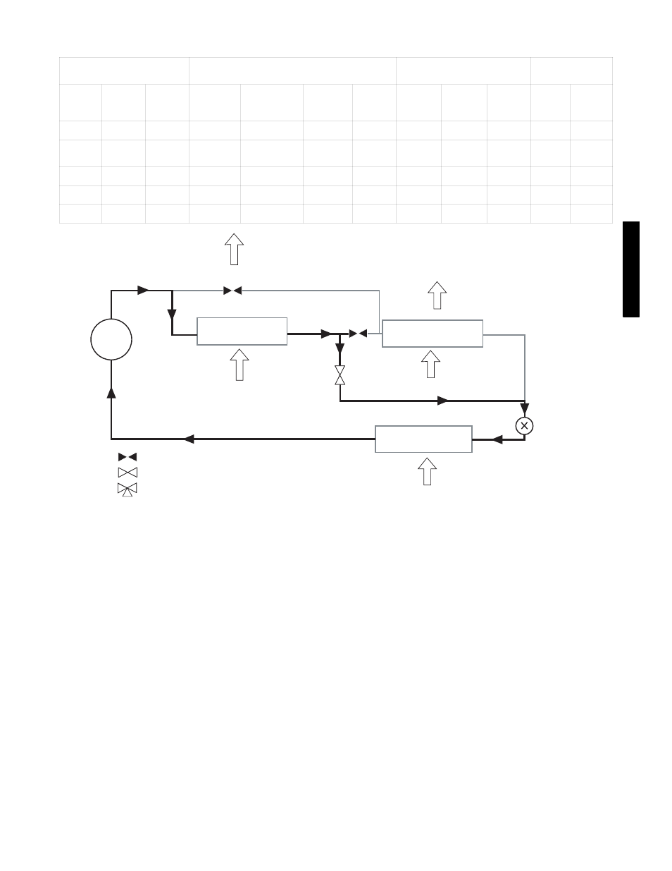
COMP
COND COIL
HUMIDI-MIZER COIL
EVAP COIL
INDOOR ENTERING
AIR
OUTDOOR AIR
METERING
DEVICE
CLOSED VALVE
OPEN VALVE
3-WAY VALVE
RH1.x
RH2.x
CV.x
C07003
Fig. 9 −
Normal Cooling Mode — Humidi−MiZer
t System
48/50PG03−16
48/50PG and PM