Carrier 39E User Manual
Central station air-handling units index
Attention! The text in this document has been recognized automatically. To view the original document, you can use the "Original mode".
Number One
AirConditbning
Maker
Division of
Carrier Corporation
Carrier Parkway • Syracus
N Y 13221
t.-
Roll Filter Sections
Central Station Air-Handling Units
INDEX
INSTALLATION
Page
Step 1 — Verify Shipment with
Shipping Order............................................... 1
Step 2 — Rig Roll Filter Section .......................... 1
Step 3 — Suspend Roll Filter Section....................1
Step 4 — Make Airway Connection...................... 1
Step 5 — Review RFS Components...................... 1
Step 6 — Install Power and Control Wires ... 1
Step 7 — Install Roll Filter Media.........................8
START-UP
Page
Step 8 — Perform Electrical Control
System Checkout........................................... 9
SERVICE
Replacing Dirty Filter Media............................... 10
Media Runout Switch.......................................... 10
Pressure Switch................................................... 11
Motor Gear-Drive Assembly............................... 11
Media Tension Brake.......................................... 11
Shear Pin............................................................. 11
Cleaning and Lubrication.................................... 11
INSTALLATION
Step 1 — Verify shipment with Shipping
Order
— Roll filter sections (RFS) are designed to
be bolted to standard Carrier 39E Central Station
Air-Handling Unit section without modification.
They may also be installed in field-fabricated duct
systems. Sections are identified as:
MODEL NO.*
APPLICATION
V-PH-HZ
AMPS
HP
39ER_A
(RFS1)
39ED_B
(RFSI)
39ED C (RFS3)
Outdoor, Automatic
Indoor, Automatic
Indoor, Manual
120-1-60
3.2
1/10
39ER_D
(RFS5)
39ED_E
(RFS5)
39ED F (RFS7)
Outdoor, Automatic
Indoor, Automatic
Indoor, Manual
230-1-50
1/10
*Sizes available for each model are shown in Fig
3
If shipment is incomplete, contact Carrier. File
damage claims with transportation agency.
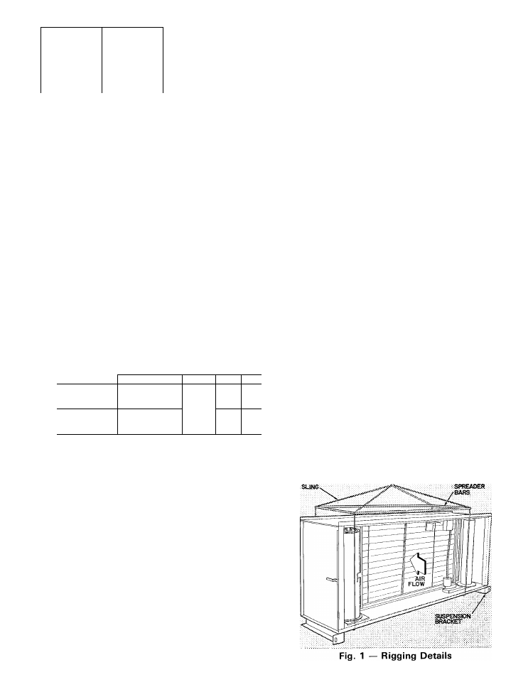
Step 2 — Rig Roll Filter Section
— Section is
designed for overhead rigging only. Do not removS
shipping skids until RFS is ready to be moved to
final location. Whenever RFS is moved, use slings
and spreader bars to prevent damage to enclosure
(Fig. 1). Brackets on entering air end of section are
for suspension and are not to be used for rigging.
Refer to base unit installation instructions as
required.
Step 3 — Suspend Roll Filter Section
— Sec
tions are supplied with suspension brackets on air
inlet end of channel leg supports (Fig. 1). Unit sizes
08 thru 57 may be suspended by these brackets and
by downstream component bolted to outlet flange.
Size 90 may not be suspended.
Step 4 — Make Airway Connection
— Holes in
RFS flanges match holes in 39E base unit sections.
Assemble sections using fasteners shipped in cloth
bag in RFS. For outdoor installation, apply black
caulking gasket on inlet and outlet flanges. Gasket
is shipped in RFS.
Step 5 — Review RFS Components
— Fa
miliarize installer with RFS interior before proceed
ing with installation of power wiring and filter media
roll. This simplifies installation and prevents
damage to equipment. Refer to Fig. 2 thru 5.
Step 6 — Install Power and Control Wires —
Junction box is located on right-hand side of RFS
as shown in Fig. 2 and 3. Install a separate field-
supplied power disconnect. On 39ER roof-curbed
units, route wires internally. Install all outdoor
wiring in accordance with local codes. Connect to
pigtails LI and L2 provided. Also connect green
ground wire found in junction box.
Tex/ continued on page 8
© Carrier Corporation 1978
Form 39E-11SI