Wiring issues, Installation wiring considerations, Troubleshooting wiring problems – KMC Controls FlexStat Operation Guide User Manual
Page 39: Ensure wiring is correct. see, Wiring issues on, Er and network lines.see, Wiring, Caution
FlexStat 39
Operation Guide, Rev. R
Wiring Issues
Installation Wiring Considerations
CAUTION
To avoid damage from ground loops and other
communication issues in networked FlexStats,
correct phasing on network and power
connections on ALL the networked controllers
is critically important.
• Because of the many connections (power,
network, inputs, outputs, and their respective
grounds or switched commons), be sure wiring is
well planned before installation of conduit!
• For information on principles and good practices
when connecting an MS/TP network, see
• To prevent excessive voltage drop,
use a conduc-
tor size that is adequate for the wiring length!
Allow plenty of “cushion” to allow for transient
peaks during startup.
• Make sure that conduit for all wiring has ad-
equate diameter for all necessary wiring. Using
1-inch conduit and junction boxes is recom-
mended!
• Use external junction boxes above the ceiling or
in another convenient location as needed to make
connections that run to the FlexStat’s junction
box.
• Using multiple conductor wires for all inputs
(e.g., 8 conductor) and outputs (e.g., 12 conduc-
tor) is recommended. Grounds for all the inputs
can be combined on one wire.
Troubleshooting Wiring Problems
• Review the wiring information in the relevant
FlexStat installation guide.
• Remove the FlexStat from the backplate and
inspect the terminals for loose or shorted wires.
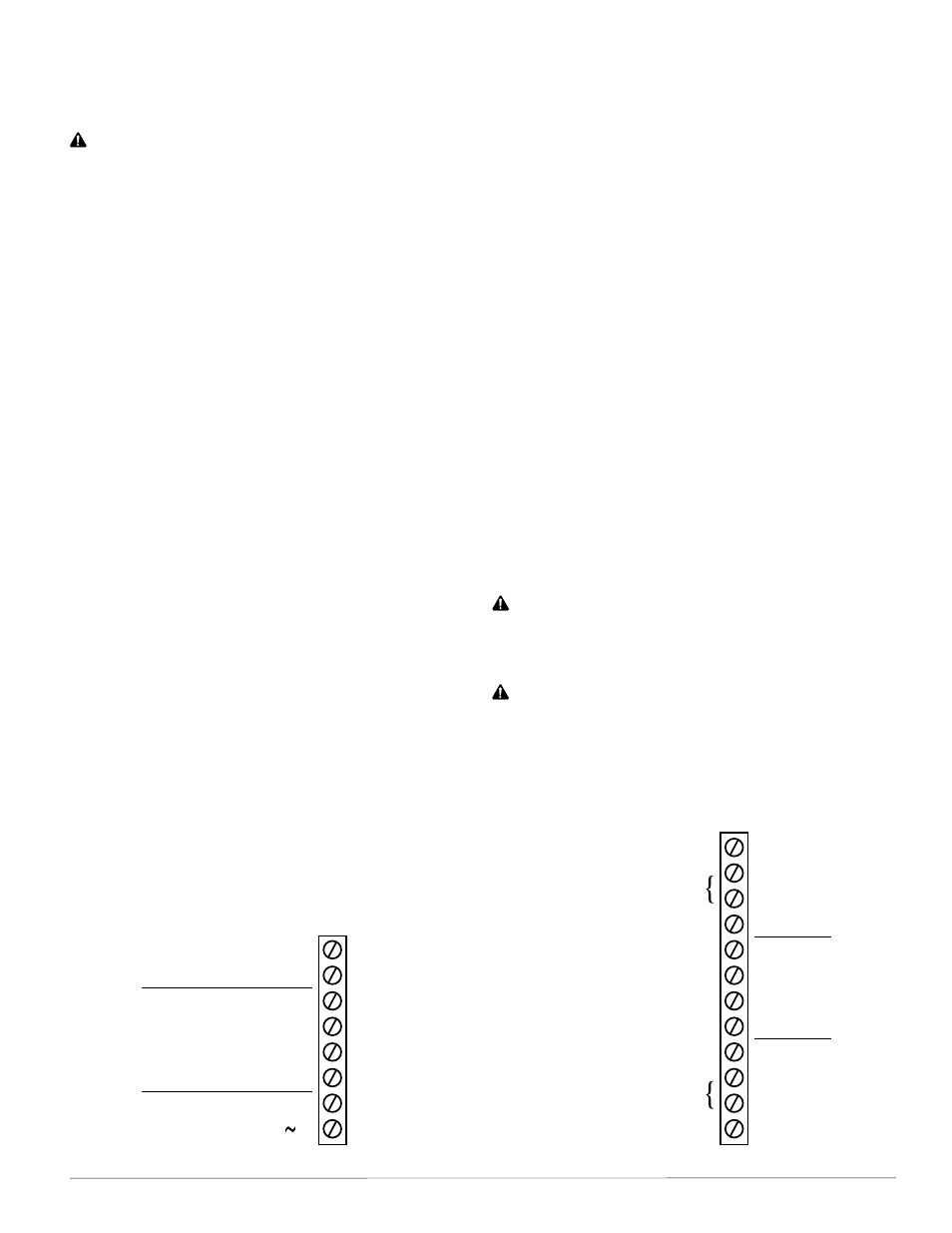
• Use a voltmeter and ohmmeter to check the
terminals for expected values. See the illustration
below and the Connections and Wiring section of
the relevant FlexStat Installation Guide.
NOTE: Voltage on the BACnet MS/TP terminals
changes according to the signals (passing
of the token) between controllers on the
network. No voltage may indicate a bad
connection or simply no active network.
NOTE: Wiring must be adequate to avoid
excessive voltage drop on long
runs! Allow plenty of “cushion” in
measurements A meter may be too slow
to register transient dips or peaks during
startup. See
.
• Check the wiring at the connected devices.
+B
–A
IN4
IN3
GND
IN2
Common/–/C
Phase/ /R
Analog 9
GND 7–9
Analog 8
Analog 7
Relay 6
SC 4–6
Relay 5
Relay 4
Relay 3
SC 1–3
Relay 2
Relay 1
Outputs
NOTE: Values Shown Are Approximate!
BACnet
MS/TP
Network
Inputs
24 VAC
NOTE: SC = Switched (Relay) Common, Should
Have the Phase Side of 24 VAC Connected
(Wiring Inputs
and Outputs
Dependent on
Application)
24 VAC
}
}
10K Ohms (Thermistor)
or
O Ohms (Closed Contact)
0.1–0.2 VDC (If Network
Token Passing is Present)
}
24 VAC
(Jumper to
Turn Device
On Manually)
NOTE: BAC-1xxx63 Backplate Terminals Shown
with FlexStat Removed; Outputs and Inputs
Vary According to Application
Resistance
Dependent
on Device
Terminal Voltages and Resistances with FlexStat REMOVED from Backplate
CAUTION
Do not mistakenly connect 24 VAC to an analog
output ground. This is not the same as a relay’s
switched common. See the backplate’s terminal
label for the correct terminal.
CAUTION
Relays are for Class-2 voltages (24 VAC) only.
Do not connect line voltage to the relays!