KMC Controls SAE-1062 User Manual
Installation guide, Carbon dioxide (co, Detectors
SAE-1011/1012/1062 Carbon Dioxide (CO
2
) Detectors
1
Installation Guide
Installation Guide
Carbon Dioxide (CO
2
) Detectors
SAE-1011/1012/1062
General Information 1
Mounting 1
SAE-1011/1012 Space Mount 1
SAE-1062 Duct Mount 2
Maintenance 6
Troubleshooting Tips 6
Accessories 6
Models 6
Important Notices 6
Specifications 6
SAE-1011/1012 Space Mount
Install the unit at least five feet above the floor of
the area to be controlled. Do not install near doors,
windows, supply air diffusers, or other known air
disturbances. Avoid areas where the detector is
exposed to vibrations or rapid temperature changes.
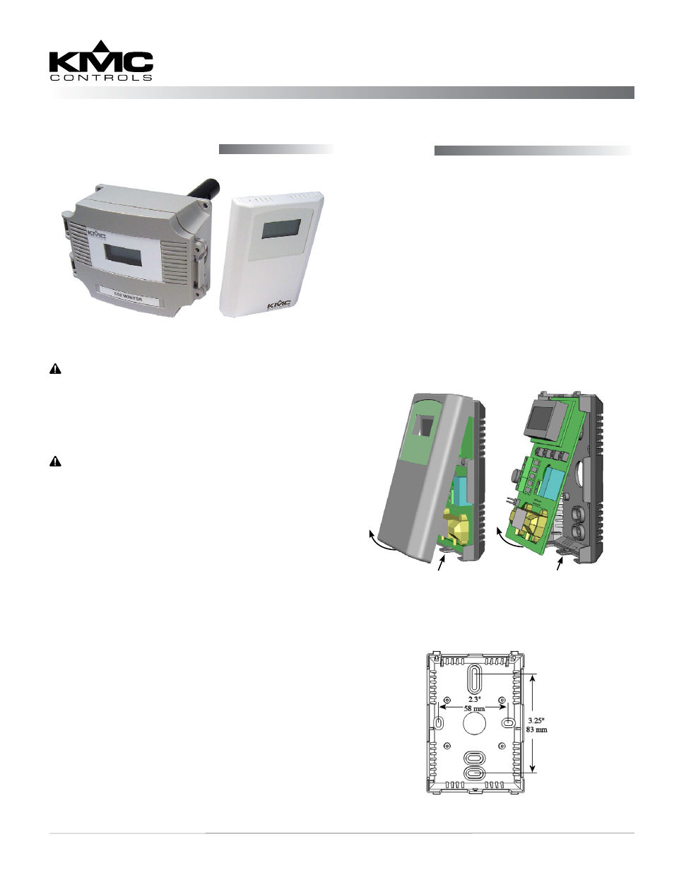
1. Remove the Phillips-head screw on the bottom
edge of the cover. (See Illustration 1.)
2. The cover is hooked to the base/backplate at the
top edge and must be removed from the bottom
edge first. Tip the cover away from the base and
set it aside. (If necessary, use a small screwdriver
to carefully pry each bottom corner.)
Mounting
WARNING
Do not use in an explosive or hazardous
environment, with combustible or flammable gases,
as a safety or emergency stop device, or in any other
application where failure of the product could result
in personal injury.
CAUTION
Read these instructions carefully before installing
and commissioning the CO
2
detector. Failure to do
so may result in product damage.
Strong shock or vibration may affect the calibration
of the SAE-1011/1012/1062. Be careful to not
drop the detector while installing or calibrating
it. Take electrostatic discharge precautions during
installation. Do not exceed the device ratings.
NOTE: The SAE-1011/1012/1062 models replace
the older SAE-1001/1002/1051 models.
For the installation and configuration
information on the older models, see the
SAE-1001/1002/1051 installation guide (717-
019-37).
NOTE: The IEI-1011 LCD display module (used
with the SAE-1001/1051 models for
configuration) does not apply to the SAE-
1011/1012/1062 models since they each have
permanent LCD displays. The display of
the SAE-1011, however, is hidden when its
cover is closed.
NOTE: See the SAE-1011/1012/1062 data sheet for
specifications and additional information.
Remove Screw and
Remove Cover
Unsnap Board
and Remove
Illustration 2—SAE-1011/1012 Backplate
Illustration 1—SAE-1011/1012 Cover and Board Removal
General Information
SAE-1012
(Space)
SAE-1062
(Duct)