KMC Controls TPE-1483 Series(2008 and later) User Manual
Installation guide, Wet-wet differential pressure transducers, Mounting 1 plumbing 1 wiring 2 set-up 2
TPE-1483 Series Wet-Wet Differential Pressure Transducers
1
Installation Guide
Installation Guide
Wet-Wet Differential Pressure Transducers
TPE-1483 Series
Mounting 1
Plumbing 1
Wiring 2
Set-Up 2
Configuration 2
Jumper Settings
Range 3
Bidirectional 3
Port Swap
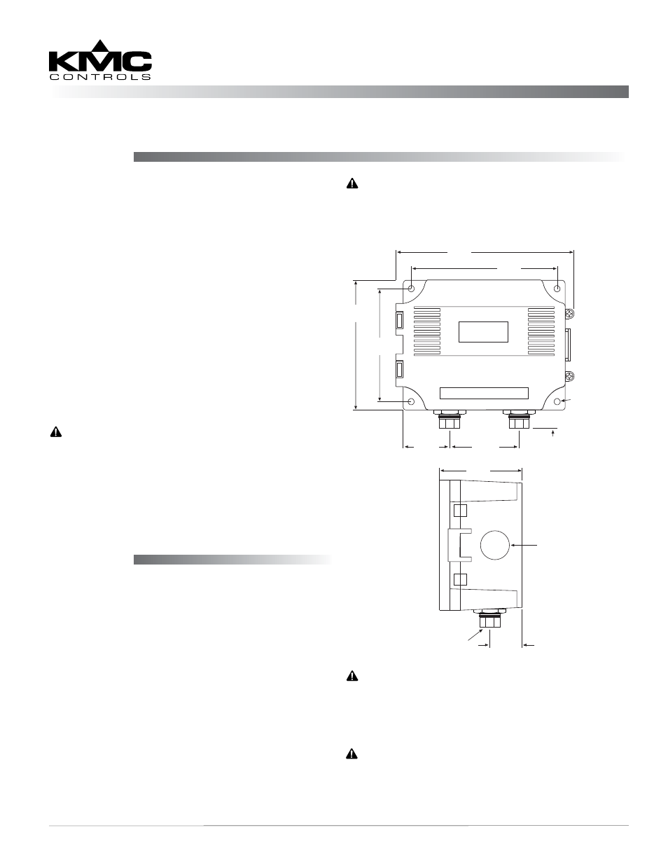
Mounting
Avoid locations with severe vibrations or excessive
moisture. The enclosure has a standard 1/2" conduit
opening and may be installed with either a conduit
coupler or a cable gland type fitting.
1. Mount on a vertical surface with the pressure
ports on the bottom.
2. Use screws in the tab holes to fasten the assembly
to the mounting surface.
3. Ensure there is enough space around the unit to
make the pressure and electrical connections.
Plumbing
NOTE: The output signal indicates a positive
value when the pressure is higher on the
High port than the Low port. As a default,
the High port is on the left and the Low
port is on the right (as shown on the circuit
board). However, a switch on the circuit
board can reverse this to correct for a
plumbing error. (See the Port Swap section
on page 3.)
1. Use appropriately rated pressure tubing for the
1/8" NPT female connections.
2. Arrange the tubing to minimize stress on the
connections.
NOTE: This document is for units available start-
ing in late 2008. See the original installation
guide available on the KMC web site for in-
stallation and configuration information on
older units with a different case and board.
CAUTION
Ensure that the maximum individual port
pressure does not exceed the maximum
pressure range of the unit.
WARNING
Do not use:
• In an explosive or hazardous environment.
• With combustible or flammable gasses.
• As a safety or emergency stop device.
• In any other application where failure of the
product could result in personal injury.
CAUTION
Do not allow debris to get into the pressure
ports since contamination can damage the
sensor.
CAUTION
Use electrostatic discharge precautions during
installation.
114.3 mm
4.5"
64 mm
2.5"
100 mm
3.95"
Ø 0.850”
Mounting Holes
(X4) Ø 0.200”
88.9 mm
3.5"
145 mm
5.7"
1/8” NPT Female
34.93 mm
1.375"
19 mm
“Low”
Port
“High”
Port
0.75"
25.4 mm
1"
53.98 mm
2.125"