KMC Controls CTE-5201-16 User Manual
Installation and operation guide, Mounting, Mounting 1
CTE-5201
1
Installation and Operation Guide
Mounting the Thermostat
1. If the thermostat is
locked on the backplate,
turn the two hex screws
(in the two outermost
holes) in the backplate
CLOCKWISE until they (just) clear the cover.
Swing the thermostat up and away from the
backplate to remove it.
CAUTION
To prevent damage to the board, do not insert
a screwdriver into any holes other than the two
outermost holes. To prevent mounting screw heads
Installation and Operation Guide
Electronic Room Thermostat (Modular)
CTE-5201
Mounting
Rough-in Preparation
For optimum temperature sensor performance, the
thermostat must be mounted on an interior wall
and away from heat sources, sunlight, windows,
air vents, and air circulation obstructions (e.g.,
curtains, furniture).
Complete rough-in wiring prior to installation:
• Route the cable from the thermostat location to
the actuator to which it will connect. See
.
• If needed, install the HMO-1161 mounting
backplate. See
Additional Information on page 4
.
from touching the circuit board in the thermostat, use
only the mounting screws supplied by KMC Controls.
Using other screws may damage the thermostat. Do
not turn screws in farther than necessary to remove
the cover.
2. Route the cable through the backplate.
3. With the hex screws toward the
floor, fasten the backplate to the
outlet box with the supplied screws.
(The backplate mounts directly on
vertical 2 x 4 inch boxes, but re-
quires an HMO-1161 wall mounting
plate for horizontal or 4 x 4 boxes.)
4. Insert the modular end of the cable
into the jack of the thermostat.
5. Place the top of the thermostat over the top of
the mounting base and swing it down over the
hex screw brackets. Be careful not to pinch the
wiring.
6. Back the hex screws out of the backplate brackets
(counterclockwise) until they engage the ther-
mostat and hold it in place.
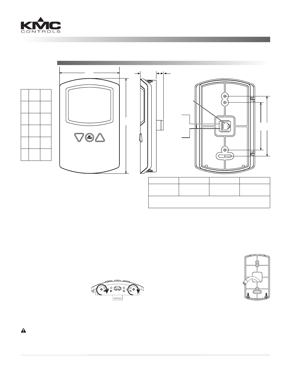
A
B
C
E F
RJ-12
Modular
Connector
D
Pin 6
Pin 1
Modular to Modular (HSO-22xx Cable)
Modular to Leads (HSO-5012 Cable) 2
Turn On Backlight 3
Change Setpoint
Start Unoccupied Mode 3
Toggle Between °F and °C
Calibration (Temperature Offset)
Pin 1 and 6
Pin 2 and 5
Pin 3
Pin 4
N/C
Common
Supply
(14–19 VDC)
Output
(2–10 VDC)*
*0 VDC during Unoccupied Off mode when temperature stays
above 50° F
A 3.25
in.
83
mm
B 5.16
in.
116
mm
C 0.88
in.
22
mm
D 0.38
in.
10
mm
E 2.58
in.
66
mm
F 3.25
in.
83
mm