KMC Controls THE-1102 User Manual
Installation guide, Mounting, Mounting 1
THE-1102
1
Installation Guide
cover. Do not use excessive force and deform or
break the tab.
2. Carefully pull the cover from the base.
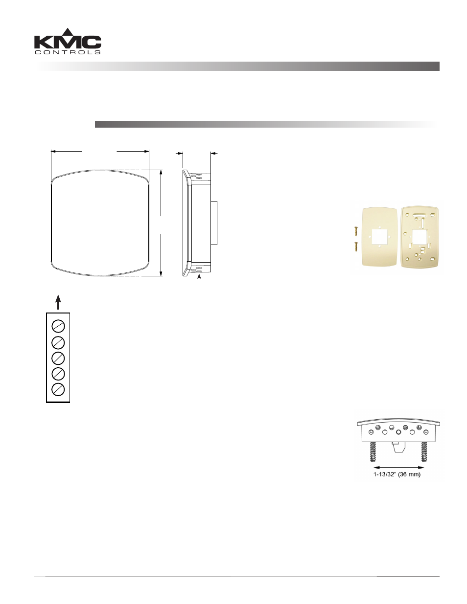
Handy Box Installation (Recommended)
1. Mount an HMO-6036
wall plate to the handy
box using the two screws
provided.
2. Remove the THE-1102’s
cover from the black base
(see the Location and
Cover Removal section).
3. With the plastic tab button on the bottom, attach
the base to the backplate using the two screws
provided.
4. Connect the wiring (see the Wiring section).
5. Reinstall the cover.
Hollow Wall Installation
1. Remove the THE-1102’s cover from the black base
(see the Location and Cover Removal section).
2. Using the base as a
template, drill two holes
for mounting screws
(7/64 inches or 3 mm in
diameter and 1.4 inches,
1-13/32 inches, or 35.6 mm
apart) and cut a center
hole for the terminal block.
3. With the plastic tab button on the bottom, attach
the base to the wall using two #6 self-threading
screws. (Plastic anchors are recommended, and
the size of the holes will then need adjusting.)
4. Connect the wiring (see the Wiring section).
5. Reinstall the cover.
Installation Guide
Humidity Transmitter w/ Temperature Sensor
THE-1102
Mounting
Location and Cover Removal 1
Handy Box Installation (Recommended)
Location and Cover Removal
Install the THE-1102 on an inside wall where it can
sense the average room temperature/humidity and
be away from direct sunlight, heat sources, windows,
air vents, and air circulation obstructions (curtains,
furniture, etc.). It can be mounted on a hollow wall
or (with an HMO-6036) to a 2 x 4 inch handy box.
The cover is held to the black base by three small
pegs that fit in the holes of the cover. The bottom peg
is on a tab and snaps into the center bottom hole.
1. With a small Phillips screwdriver or hex wrench,
press in and hold the plastic tab button that
snaps into the center hole on the bottom of the
2-1/4" (57 mm)
2-7/16"
(62 mm)
5/8"
(16 mm)
Up (Toward Ceiling
at Installation)
Tab Button
Temperature Output
(10K Thermistor)
Humidity Output
(0 to 5 VDC)
Signal Ground
– Power Ground
(A)
(B)
(C)
(F)
(D)
+ 10 to 15 VDC Power
NOTE: The Thermistor
Temperature
Output
Terminal “A”
should be
at the top of
the terminal
strip after
installation.