KMC Controls CTC-1622 User Manual
Installation guide, Mounting, Mounting 1
CTC-1621/1622
1
Installation Guide
Installation Guide
Two-Pipe, Single-Setpoint, Pneumatic, Room Thermostats
CTC-1621/1622
Mounting
Location
For optimum performance, the thermostat must be
mounted on an interior wall and away from heat
sources, sunlight, windows, air vents, and air circula-
tion obstructions (e.g., curtains, furniture). Units may
be mounted horizontally or vertically to either a 2" x
4" electrical box or a hollow wall.
1. Using the template printed on the HMO-5023
package, make a 2-11/16" x 1-1/2" cutout.
2. Loosely mount the bracket to the thermostat with
the two 6-32 x 2" screws supplied.
3. Make connections (see the Connections section).
4. Insert the bracket diagonally through the wall.
5. Center the thermostat and tighten the screws.
Scale Plate
All adjustments must be made with the scale plate
removed. Complete adjustments before installing the
scale plate. (See the Adjustments section.)
1. Remove the gauge tap’s rubber cap.
2. Slide the scale plate under the setpoint indicator.
3 Insert the retaining pins (two supplied), twisting
to lock into place.
4. Reinstall the gauge tap’s rubber cap.
Setpoint Options
If the setpoint indicator is not needed, simply snip
off the indicator with a wire cutter. Limit or lock the
range of the setpoint by installing setpoint stops
(HFO-0027) in the slider track.
Cover
Covers are available in two styles:
♦
Window-insert covers include a symbol-coded
label strip (HPO-1320) for setpoint indication.
Apply the label in the recessed area underneath
the window.
♦
Blank covers require the removal of the setpoint
thumb adjuster. Insert a small screwdriver in the
slot between the thumb adjuster and the cam and
pry apart. Discard the adjuster.
To install a cover:
1. Ensure the thermostat is mounted securely and
the gauge tap cap and accessories are installed.
2. Slide the cover over the base.
3. Using a 1/16" hex wrench, turn both cover
mounting screws on the thermostat base CCW
(outward) until the cover is secured. (See the
illustration in the Adjustments section.)
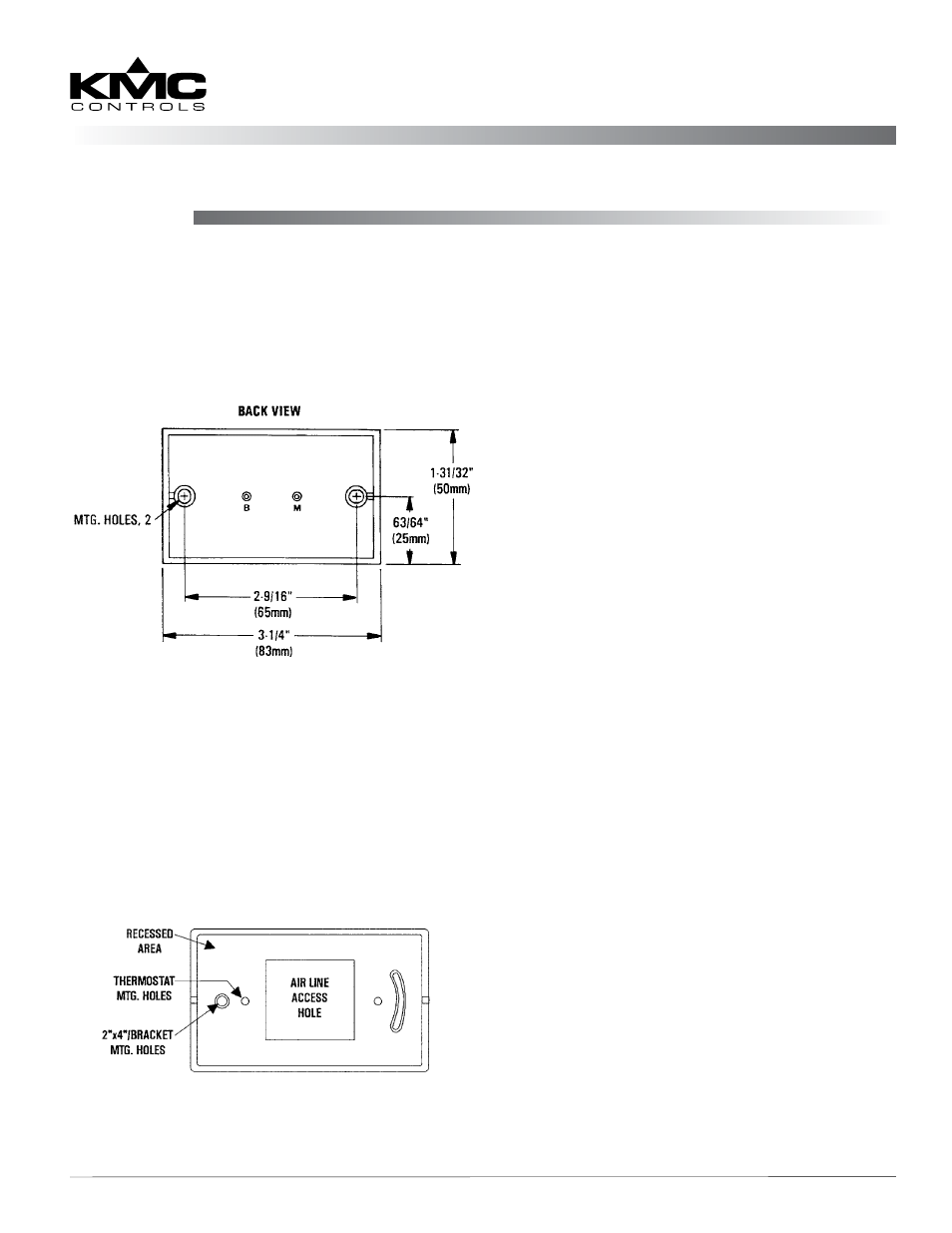
Electrical Box Mounting
1. Attach the desired HMO-50xx backplate to the
box with the two 6-32 screws supplied.
2. Level the box using the slot in the backplate.
3. Fit the aluminum plate into the recess.
4. Pass the 3/32" ID tubing through access hole.
5. Make connections (see the Connections section).
6. Mount the thermostat to the backplate with two
6-20 x 2" screws supplied with the thermostat.
Maintenance 2
Important Notices 2
Additional Resources
Hollow Wall Mounting
NOTE: Thermostats may be mounted on hollow
walls up to 5/8" with the HMO-5023 kit.
CTC-1621/1622 Back
HMO-50xx