Example 1, Example 2, Analog inputs 5 – Rockwell Automation 20A PowerFlex 70EC/700VC User Manual
Page 9
Analog Inputs
5
Example 1
− [Anlg In Config], bit 0 = “0” (Voltage)
− [Speed Ref A Sel] = “Analog In 1”
− [Speed Ref A Hi] = 60 Hz
− [Speed Ref A Lo] = 0 Hz
− [Analog In 1 Hi] = 10V
− [Analog In 1 Lo] = 0V
This is the default setting, where 0 volts represents 0 Hz and 10 volts represents 60 Hz providing 1024
steps (10 bit analog input resolution) between 0 and 60 Hz.
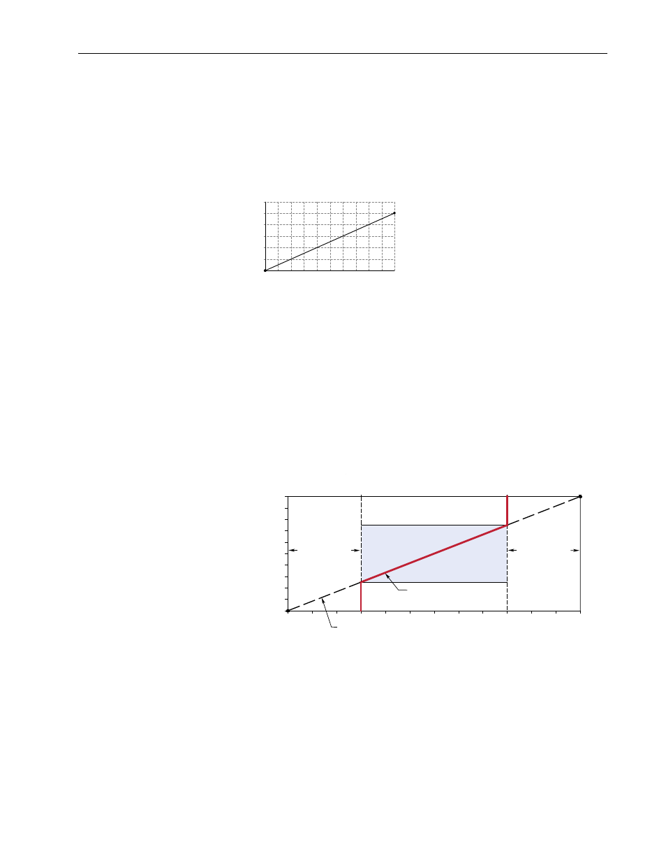
Example 2
Consider the following setup:
− [Anlg In Config], bit 0 = “0” (voltage)
− [Speed Ref A Sel] = “Analog In 1”
− [Analog In1 Hi] = 10V
− [Analog In1 Lo] = 0V
− [Speed Ref A Hi] = 60 Hz
− [Speed Ref A Lo] = 0 Hz
− [Maximum Speed] = 45 Hz
− [Minimum Speed] = 15 Hz
This configuration is used when non-default settings are desired for minimum and maximum speeds,
but full range (0-10V) scaling from 0-60 Hz is still desired.
In this example, a deadband from 0-2.5 volts and from 7.5-10 volts is created. Alternatively, the analog
input deadband could be eliminated while maintaining the 15 and 45 Hz limits with the following
changes:
− [Speed Ref A Lo] = 15 Hz
− [Speed Ref A Hi] = 45 kHz
2
4
6
8
10
12
6
0
12
18
Output Hertz
Input Volts
24
30
36
42
48
54
60
Motor Operating Range
Command Frequency
15 Hz
45 Hz
60 Hz
0 Hz
Frequency Deadband
Slope defined by (Analog Volts)/(Command Frequency)
Frequency Deadband
7.5-10 Volts
0-2.5 Volts
[Speed Ref A Lo]
[Speed Ref A Hi]
10V
0V
[Analog In1 Hi]
[Analog In1 Lo]
[Maximum Speed]
[Minimum Speed]