Rockwell Automation 20A PowerFlex 70EC/700VC User Manual
Page 106
102
Speed Regulation
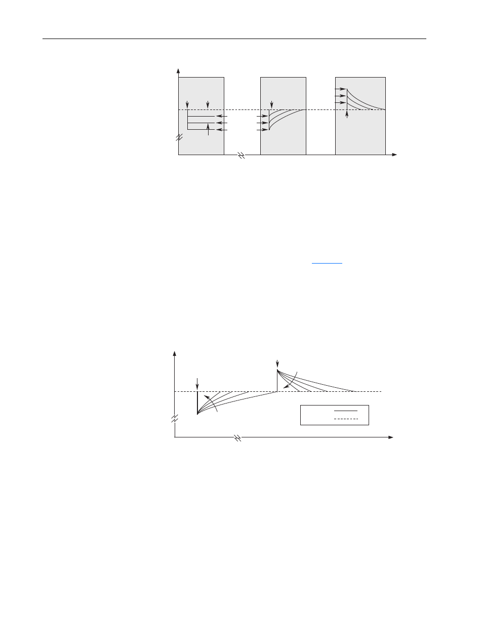
Figure 18 Rotor Speed with/without Slip Compensation
Internally, the drive converts the rated slip in RPM to rated slip in frequency. To
more accurately determine the rated slip frequency in hertz, an estimate of flux
current is necessary. This parameter is either a default value based on motor
nameplate data or the auto tune value. The drive scales the amount of slip
compensation to the motor rated current. The amount of slip frequency added to the
frequency command is then scaled by the sensed torque current (indirect
measurement of the load) and displayed.
Slip compensation also affects the dynamic speed accuracy (ability to maintain
speed during “shock” loading) as illustrated in
Figure 19
. Initially, the motor is
operating at some speed and no load. At some time later, an impact load is applied
and the rotor speed decreases as a function of load and inertia. And finally, the
impact load is removed and the rotor speed increases momentarily until the slip
compensation is reduced based on the applied load.
The responsiveness to an impact load can be adjusted through [Slip Comp Gain];
however too large of a gain can cause unstable operation and overshoot.
Figure 19 Rotor Speed Response Due to Impact Load and Slip Com Gain
Slip Compensation
Active
Open Loop
Mode
Time
Rotor Speed
0
0
Load
Applied
Load
Applied
No Load
Slip @
F.L.A.
0.5 p.u. Load
1.0 p.u. Load
1.5 p.u. Load
0.5 p.u. Load
1.0 p.u. Load
1.5 p.u. Load
Slip Compensation
Active
Load
Removed
Time
Speed
0
0
Impact Load
Applied
Impact Load
Removed
Increasing Slip
Comp Gain
Increasing Slip
Comp Gain
Rotor Speed
Reference