Motor overload – Rockwell Automation 20A PowerFlex 70EC/700VC User Manual
Page 59
Motor Overload
55
Motor Overload
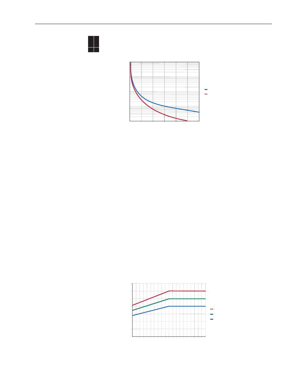
The motor overload protection feature uses an IT (inverse time) algorithm to model
the temperature of the motor and follows the same curve as a physical class 10
overload device.
[Motor NP FLA] is used by the overload feature to establish the 100% level (y axis)
shown in the graph above.
Setting the correct bit in [Fault Config x] to zero disables the motor thermal
overload. For multimotor applications (more than one motor connected to one
drive), separate external overloads for each motor are required, and the drive’s
motor overload can be disabled.
Operation of the overload is based on three parameters; [Motor NP FLA], [Motor
OL Factor] and [Motor OL Hertz].
1. [Motor NP FLA] is the base value for motor protection.
2. [Motor OL Factor] is used to adjust for the service factor of the motor. Within
the drive, motor nameplate FLA is multiplied by motor overload factor to select
the rated current for the motor thermal overload. This can be used to raise or
lower the level of current that will cause the motor thermal overload to trip
without the need to adjust the motor FLA. For example, if motor nameplate
FLA is 10 Amps and motor overload factor is 1.2, then motor thermal overload
will use 12 Amps as 100%.
Important: Some motors have a service factor that is only for use with sine
wave (non-drive) power. Check with the motor manufacturer to
see if the nameplate service factor is valid or must be reduced
when operated by a drive.
70EC
700VC
700H
✔ ✔
Motor Overload Curve
10
100
1000
10000
100000
100
125
150
175
200
225
250
Full Load Amps (%)
Trip Time
(Seconds)
Cold
Hot
Changing Overload Factor
20
40
60
80
100
120
140
0
10
20
30
40
50
60
70
80
90 100
% of Base Speed
Contin
uous Rating
OL % = 1.20
OL % = 1.00
OL % = 0.80