High resolution speed reference, Input phase loss detection – Rockwell Automation 20A PowerFlex 70EC/700VC User Manual
Page 52
48
High Resolution Speed Reference
High Resolution
Speed Reference
The high resolution speed reference provides a 32 bit (as opposed to a 16 bit) speed
reference from a communication network. The high resolution 32 bit reference is
scaled so that a value of 2147483647 corresponds to [Maximum Freq], parameter
55 if [DPI Ref Select], parameter 298 = “0, Max Freq,” or 2147483647 corresponds
to [Maximum Speed], parameter 82 if [DPI Ref Select] = “1, Max Speed.”
To use the high resolution reference, [Speed Ref A Sel] or [Speed Ref B Sel] is set
to “30, HighRes Ref.” Then [HighRes Ref], parameter 308 is used as a reference
through datalinks. A pair of datalinks (e.g. A1 and A2 or B1 and B2, etc.) must be
set to write to [HighRes Ref].
Example
The following example writes the high resolution reference to a PF70EC on Ethernet from
ControlLogix.
Drive Parameter Settings:
− [Speed Ref A Sel], parameter 90 = 30 “HighRes Ref”
− [DPI Ref Select], parameter 298 = 1 “Max Speed”
− [Data In A1], parameter 300 = 308
− [Data In A2], parameter 301 = 308
Data In A1 will contain the least significant word (LSW) of the speed reference and Data In A2 will
contain the most significant word (MSW) of the speed reference.
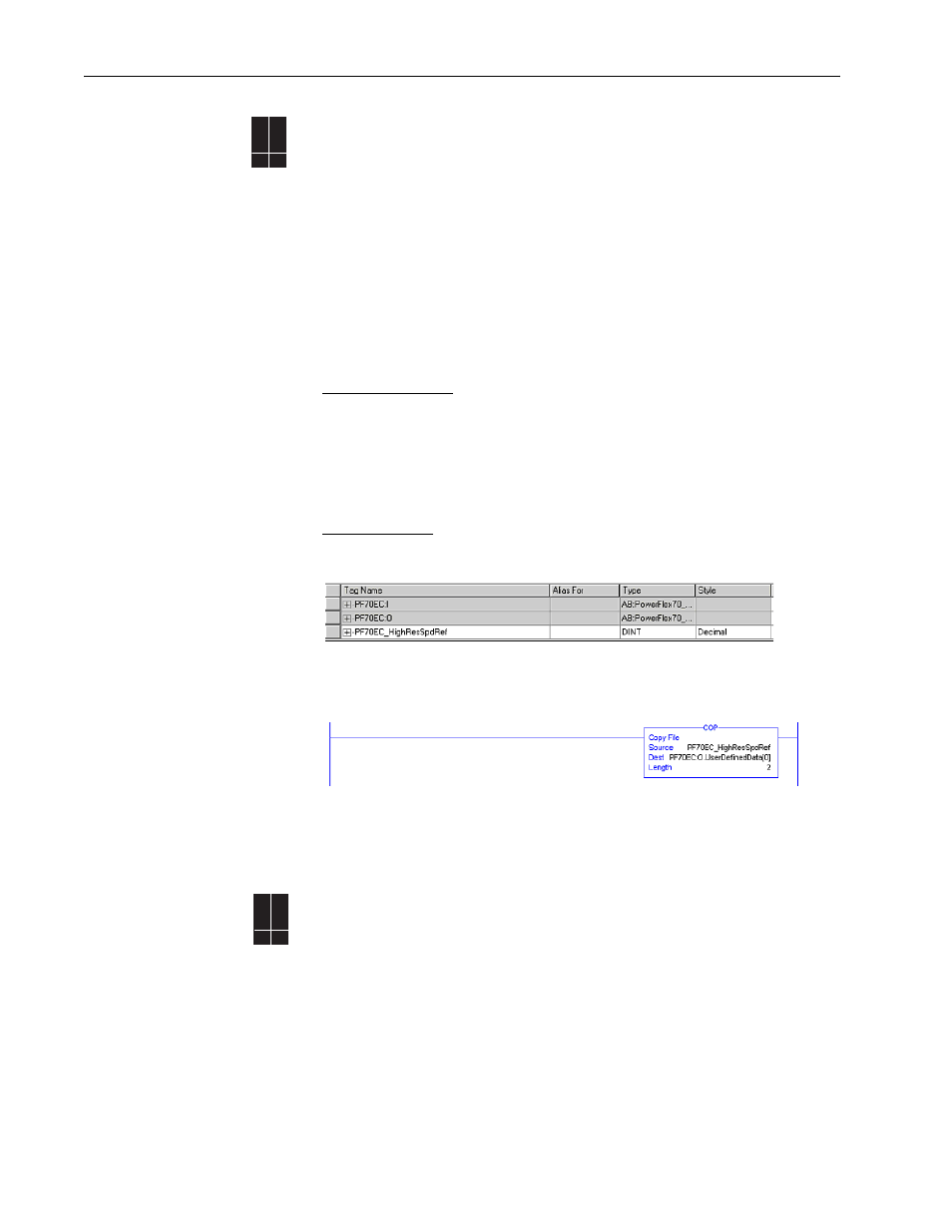
ControlLogix Program
A PF70EC is added in I/O Configuration. Then a new tag of type DINT is created for the high resolution
speed reference.
Next, the speed reference is written to the DINT tag “PF70EC_HighResSpdRef.” Using the COP
instruction, the DINT tag is copied to 2 UserDefinedData tags. The tag PF70EC:O:UserDefinedData[0]
corresponds to Data In A1 in the drive and the tag PF70EC:O:UserDefinedData[1] corresponds to Data
In A2.
Setting the tag PF70EC_HighResSpdRef to 2147483647 corresponds to [Max Speed] of the drive.
Important: In 16 bit processors such as the SLC and PLC-5, there are no DINT data types, so the high
resolution speed reference remains split as 2 separate 16-bit words.
Input Phase Loss
Detection
Occasionally, three-phase power sources can fail on one phase while continuing to
deliver power between the remaining 2 phases (single-phase). Operating above
50% output under this single-phase condition can damage the drive. If such a
condition is likely, it is recommended that Input Phase Loss Detection be enabled.
The drive can be programmed to simply turn on an alarm bit, or also fault the drive.
The drive accomplishes this by interpreting voltage ripple on the DC bus.
Configuration
•
[Drive Alarm 1], parameter 259, bit 12 - “In Phase Loss” 0 = disabled, 1 =
enabled.
•
[Fault Config 1], parameter 238, bit 8 - “In Phase Loss” 0 = disabled, 1 =
enabled
70EC
700VC
700H
✔
70EC
700VC
700H
✔ ✔