Connecting the fiber optic cable, Connecting the fiber optic cable -3 – Rockwell Automation 1756-SYNCH ControlLogix SynchLink Module User Manual User Manual
Page 51
Publication 1756-UM521C-EN-P - July 2004
Installing the SynchLink Module 4-3
Connecting the Fiber
Optic Cable
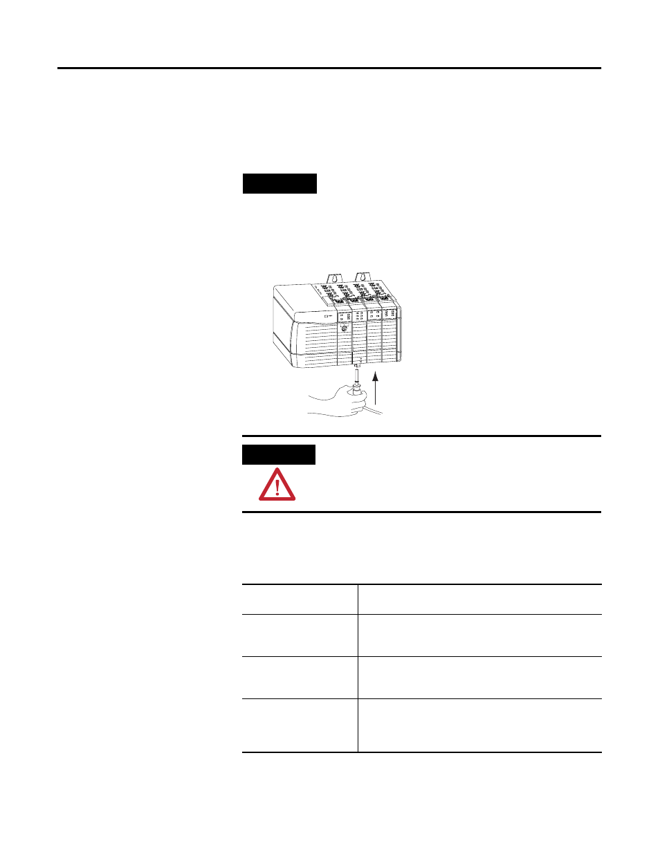
Your 1756-SYNCH module has two ports for fiber optic cables. The front
port receives data, and the rear port transmits data.
1. Remove the plugs from the ports at the bottom of the module.
2. Connect the fiber optic cables as shown below.
Figure 4.3
Table 4.2 lists the possible connections that might be made to your
1756-SYNCH module and where to connect the fiber optic cable.
This completes installation. Use the next section to remove your SynchLink
module if necessary.
TIP
Keep the plugs that were removed to connect the fiber
optic cables. When the cables are disconnected, you can
reinsert the plugs to protect the ports.
ATTENTION
Do not look directly into the fiber ports or fiber cables.
Light levels may cause damage to eyesight. The SynchLink
module is a Class 1 LED product.
Table 4.2 Making Fiber Optic Cable Connections to the 1756-SYNCH Module
If your 1756-SYNCH
module is configured to:
Make this fiber optic cable connection:
transmit data only
Connect the fiber optic cable to the rear port. The other end
of the cable should be connected to a device receiving data
over the SynchLink from your 1756-SYNCH module.
receive data only
Connect the fiber optic cable to the front port. The other end
of the cable should be connected to a device transmitting
data to your 1756-SYNCH module over the SynchLink.
transmit and receive data
1. Connect the fiber optic cable going to (i.e. transmitting
the data to) a module receiving the data to the front port.
2. Connect the fiber optic cable coming from (i.e. receiving
the data from) a module transmitting data to the rear port.
LINK
COMM
LINK
SYNC
OK
Rx(front)
Tx (rear)
31267