Daisy chain configuration -7, Daisy chain configuration – Rockwell Automation 1756-SYNCH ControlLogix SynchLink Module User Manual User Manual
Page 27
Publication 1756-UM521C-EN-P - July 2004
Time Synchronization in the ControlLogix System 2-7
Daisy Chain Configuration
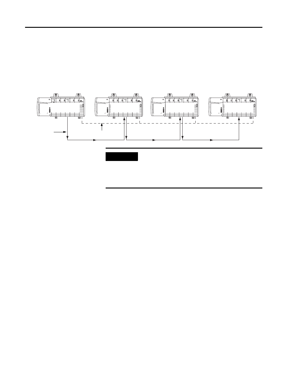
In the daisy chain configuration, the SynchLink network starts at the
Master Node and ends at an End Node. You can include Center Nodes
(shown in Figure ) in the configuration as needed.
Figure 2.6
In the daisy chain configuration the time synchronization process is
more complicated than in the star. It’s based on the following rules.
• Each node enables its transmitter right after it has received the
first message from the upstream node.
• Each node can generate and transmit the beacon signal
regardless of whether it has received one or not.
• Each node is a Time Slave of its upstream node and will attempt
to synchronize with it.
The SynchLink Time Master node must be set as the SynchLink Time
Master. Its node clock is the SynchLink system clock. After power-up,
the Master node begins to transmit a message every 50μS. As soon as
the node connected to it receives the first of these messages, it begins
to send messages to its downstream node. Eventually, all center nodes
are transmitting messages.
As soon as a node receives the first message with the beacon signal, it
starts to synchronize its node clock with the upstream node clock. The
node connected to the Master, is the first to synchronize its clock with
the SynchLink system clock. This process then propagates down the
daisy chain until all nodes are synchronized with the Master.
For an example of how to configure a Daisy Chain configuration, see
Appendix C.
42746
Master Node
Center Node
Center Node
End Node
ControlNet
SynchLink
IMPORTANT
In the daisy chain configuration, you can use a
maximum of 10 nodes, including the master and
end nodes.
Also, the only difference between Center and End
Nodes is their physical location.