D - configuring the ring configuration, Appendix d, Configuring the ring configuration – Rockwell Automation 1756-SYNCH ControlLogix SynchLink Module User Manual User Manual
Page 111: N - appendix d, E appendix d for an example, Appendix d - ri, Appendix
1
Publication 1756-UM521C-EN-P - July 2004
Appendix
D
Configuring the Ring Configuration
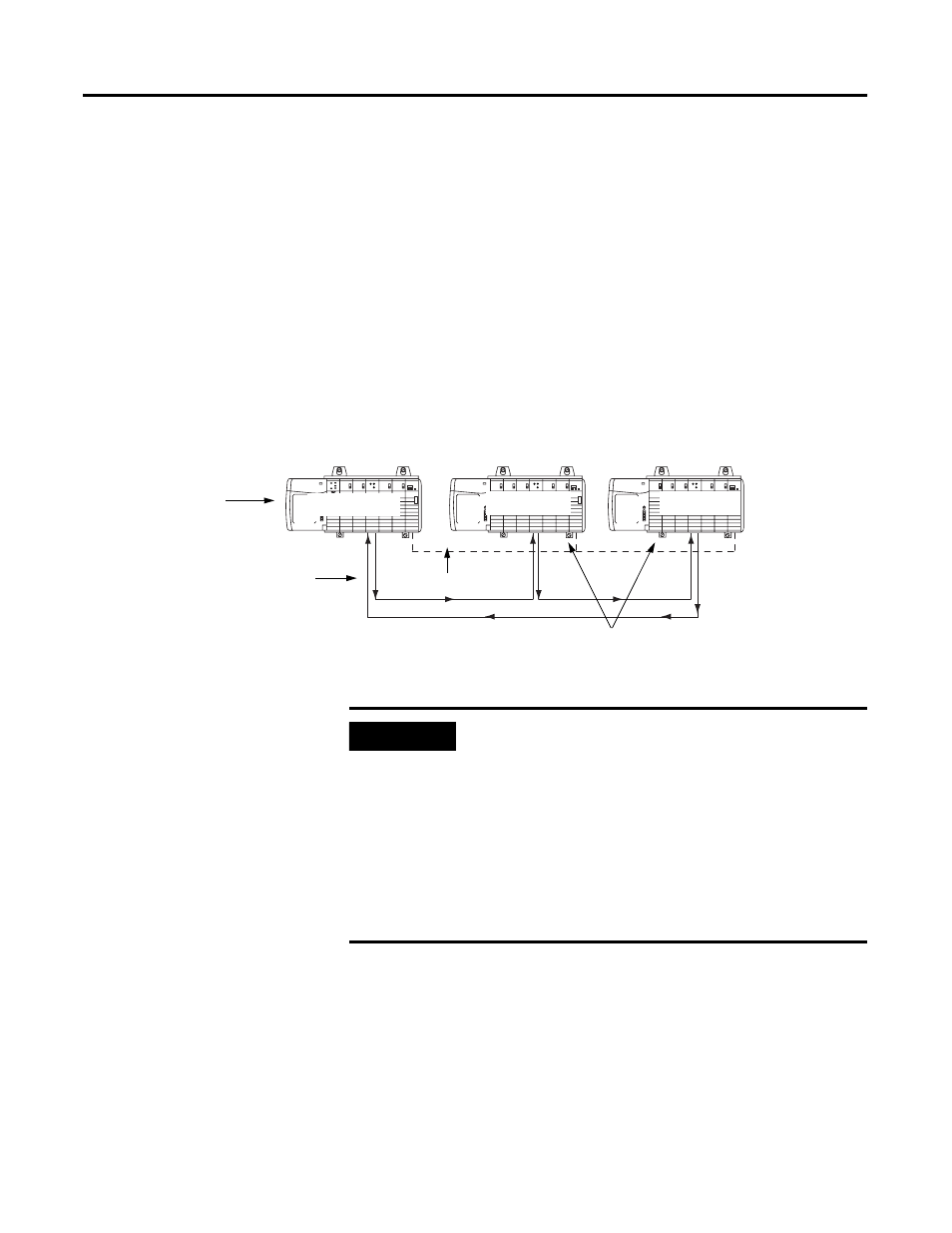
This appendix provides a sample configuration for a SynchLink system using
the Ring Configuration. The system’s physical configuration is shown in
Figure D.1. In this configuration, you must:
• configure the Master Node in an RSLogix 5000 project.
• configure the Center Node in an RSLogix 5000 project.
• configure the End Node in an RSLogix 5000 project.
Figure D.1
42883
Master Node
ControlNet
SynchLink
Center Node
Center Node
The SynchLink modules in these chassis
are configured as the CST Time Masters.
The SynchLink module in
this chassis is configured
as the Time Master for
the for the SynchLink.
IMPORTANT
You can use a maximum of 10 nodes in the Ring
configuration. In this configuration, you must configure all
chassis that are Time Slave chassis on SynchLink as CST
Time Master for the local chassis.
Also, in the Star and Daisy Chain configurations, the
Master Node does not receive data. But in the Ring
configuration, the Master Node receives data from the End
Node. Make sure the Master Node’s receive port
communications format matches the End Node’s transmit
port communications format.