Configure the output configuration tab – Rockwell Automation 1791DS-IBxxxx Guard I/O DeviceNet Safety Modules User Manual
Page 77
Rockwell Automation Publication 1791DS-UM001J-EN-P - May 2013
77
Configure Modules with the Logix Designer Application
Chapter 5
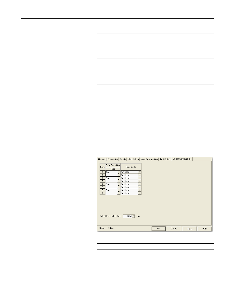
2. Assign the Point Mode
(1)
.
There is also a Test Output Fault Action parameter that can only be read or
written to via explicit messaging. If communication to the module times
out, you can set the test outputs to Clear OFF (default) or Hold Last State.
3. Click OK.
Configure the
Output Configuration Tab
This section provides a procedure for configuring safety outputs by using the
information in this table and completing the entries referring to the figure.
Follow this procedure to complete the safety output configuration.
1. From the Module Properties dialog box, click the Output Configuration
tab.
2. Assign the Point Operation Type.
(1) Directly related to safety.
Choose
Description
Not Used (default)
The standard output is disabled.
Standard
The output point is enabled for use by the GuardLogix controller.
Pulse Test
The test output is being used as a pulse test source.
Power Supply
A constant 24V is placed on the output terminal. It can be used to
provide power to a field device.
Muting Lamp Output (terminal T3,
T7, T11, and T15 only)
An indicator lamp is connected to the output. When this lamp is
energized, a burned-out bulb, broken wire, or short to GND error
condition can be detected. Typically, the lamp is an indicator used in
light curtain applications.
Choose
Description
Single
(1)
The output is treated as a single channel.
Dual (default)
The Guard I/O module treats the outputs as a pair. It always sets them
HI or LO as a matched pair. Safety logic must set both of these outputs
ON or OFF as the same time or the module declares a channel fault.
(1) Does not apply to bipolar outputs.