Relay output examples – Rockwell Automation 1791DS-IBxxxx Guard I/O DeviceNet Safety Modules User Manual
Page 57
Rockwell Automation Publication 1791DS-UM001J-EN-P - May 2013
57
Wiring Examples
Chapter 4
Relay Output Examples
Read this section for relay output examples by application. For details, refer to the
installation instructions for each catalog number.
Relay Outputs with Dual-channel Mode and External Device
Monitoring Input
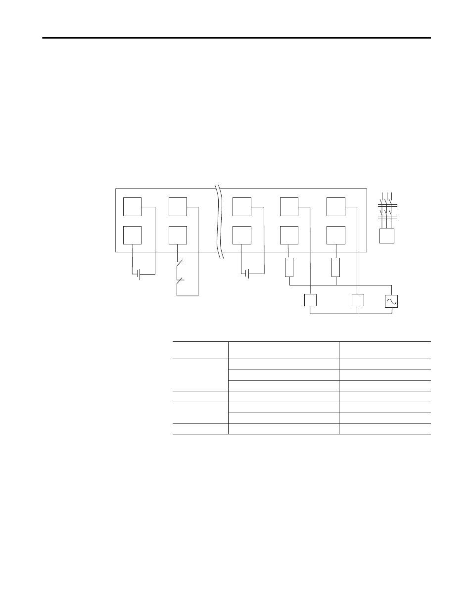
This example shows wiring and controller configuration when using a Guard I/O
module with relay outputs in dual-channel mode and an external device
monitoring input. If used in combination with the programs in a safety
controller, this wiring is Safety Category 4 in accordance with EN 954-1 wiring
requirements.
V0
I0
V1
0
1
G0
E1
E2
F1
F2
AC Supply
K1
K2
T0
G1
C0
31808-M
C1
K1
M
K1
K2
K2
, E2: 24V DC Power Source
, K2: Magnetic Contactors
Three-phase Motor
, F2: Fuses
V0, G0: Input Power Connection
V1, G1: Output Power Connection
Controller
Configuration
Parameter Name
Configuration Setting
Safety Input 0
Safety Input 0 Channel Mode
Test Pulse from Test Output
Safety Input 0 Test Source
Test Output 0
Dual-channel Safety Input 0/1 Mode
Single Channel
Test Output 0
Test Output 0 Mode
Pulse Test Output
Safety Output 0
Safety Output 0 Channel Mode
Safety
Dual-channel Safety Output 0/1 Mode
Dual-channel
Safety Output 1
Safety Output 1 Channel Mode
Safety