Rockwell Automation 1791DS-IBxxxx Guard I/O DeviceNet Safety Modules User Manual
Page 131
Rockwell Automation Publication 1791DS-UM001J-EN-P - May 2013
131
Interpret Status Indicators
Chapter 8
1791DS-IB12,
1791DS-IB8XOB8, and
1791DS-IB4XOW4
Status Indicators
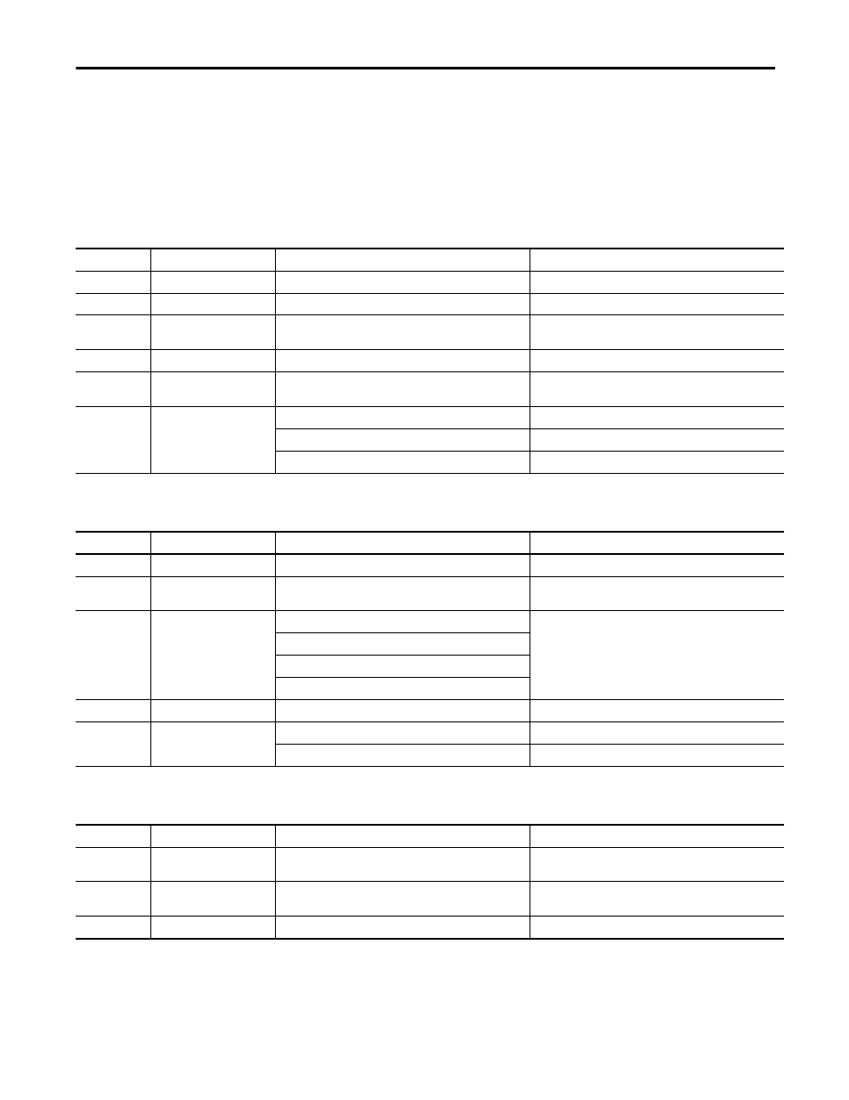
Refer to the tables for information on how to interpret status indicators on the
1791DS-IB12, 1791DS-IB8XOB8, and 1791DS-IB4XOW4 modules.
Table 3 - Module Status (MS) Indicator
State
Status
Description
Recommended Action
Solid green
Normal
Normal operating status.
None- normal operation.
Flashing green
Standby
Waiting for safety communication from the safety controller.
Wait for module to establish communication.
Solid red
Fatal fault
Hardware fault.
Check for electrical noise and eliminate the source. If the
anomaly persists, replace the module.
Flashing red
Minor fault
Switch settings incorrect.
Correct the switch settings.
Flashing green/
red
Initialization status
The module is performing initialization process or waiting for
configuration.
Wait for the configuration to complete.
Off
No power
Power is not being supplied to the module.
Supply power to the module.
Waiting for initial processing to start.
Wait for processing to start.
The module is being reset.
Wait for the module to reset.
Table 4 - Network Status (NS) Indicator
State
Status Description
Recommended
Action
Solid green
Online/connected
Network is operating normally (communication established).
None - normal operation.
Flashing green
Online/not connected
Network is operating normally, however, communication is not
established.
Verify your network and module configuration.
Solid red
Fatal link failure
Communication fault.
Correct the communication fault.
Module detected that network communication is not possible.
Node address duplication detected.
Abusive fault detected.
Flashing red
Minor communication fault
Communication timeout.
Correct the communication fault.
Off
Not online or not powered
Waiting for node address duplication check at the master.
Wait for check to complete.
The power supply is off.
Apply power.
Table 5 - Configuration Lock (LOCK) Indicator
State
Status
Description
Recommended Action
Solid yellow
Normal and locked
Normal configuration, and configuration is locked by RSNetWorx
for DeviceNet software.
None.
Flashing yellow
Normal and not locked
Normal configuration, but configuration is not locked in the
module.
None.
Off
Configuration not performed
Configuration has not been performed.
Perform the configuration.