Rockwell Automation 1791DS-IBxxxx Guard I/O DeviceNet Safety Modules User Manual
Page 134
134
Rockwell Automation Publication 1791DS-UM001J-EN-P - May 2013
Chapter 8
Interpret Status Indicators
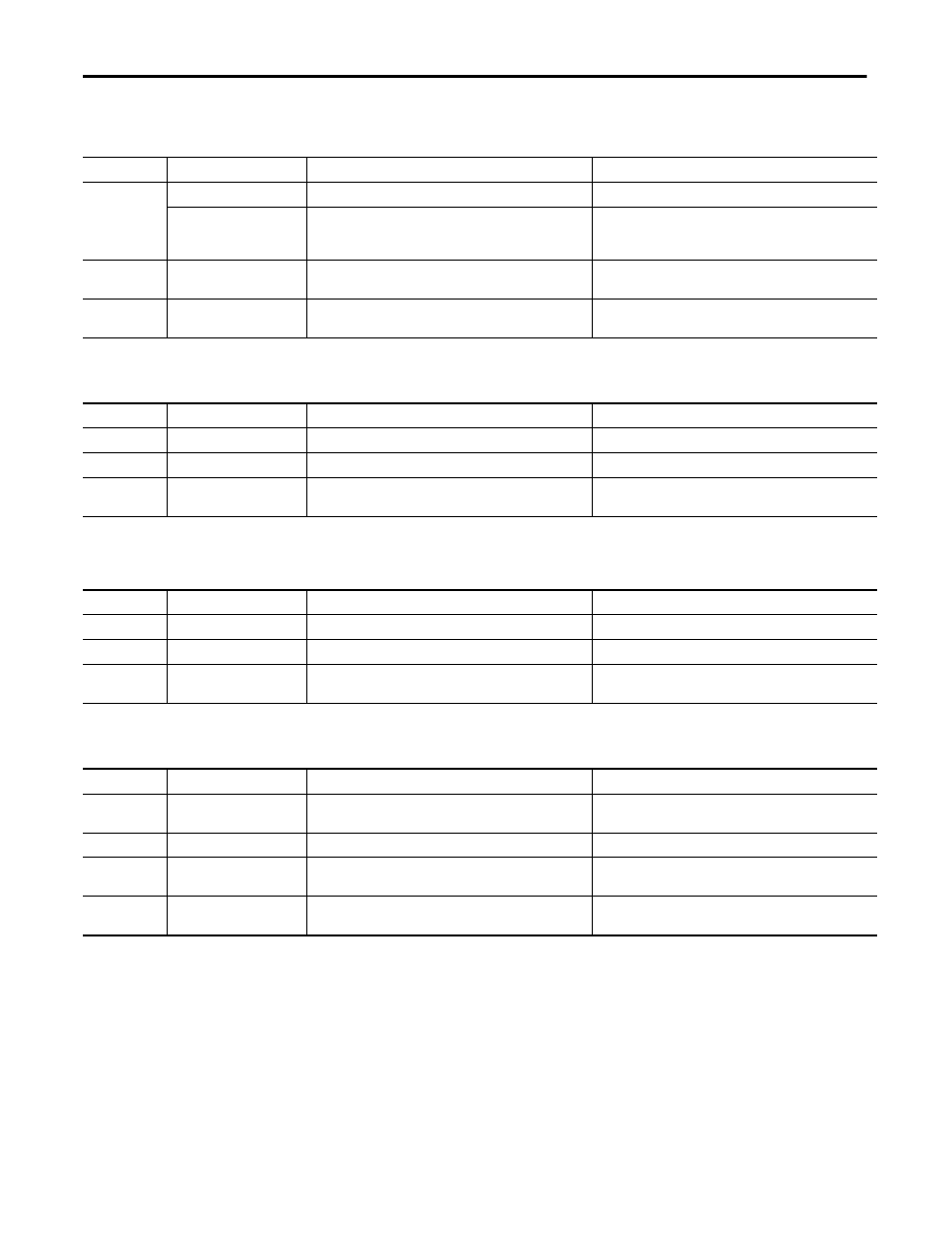
Table 12 - Configuration Lock (LOCK) Indicator
State
Status
Description
Recommended Action
Off
No configuration
Invalid configuration data.
Provide valid configuration data.
The configuration is owned by
a CIP safety originator, such as
GuardLogix software
The configuration is owned by a CIP safety originator, such as
GuardLogix software.
None.
Solid yellow
Locked
Valid configuration, locked by a network configuration tool such
as RSNetWorx for DeviceNet software.
None.
Flashing yellow
Not locked
Valid configuration, owned by a software configuration tool
such as RSNetWorx for DeviceNet software.
None.
Table 13 - 24V DC Input Power Indicator
State
Status
Description
Recommended Action
Off
No power
No power is applied.
Apply power to this section.
Solid green
Normal operation
The applied voltage is within specifications.
None.
Solid yellow
Input power out of
specification
The input power is out of specification.
Check your connectors, wiring, and voltages, For additional
information, see the applicable installation instructions.
Table 14 - 24V DC Output Power Indicator
State
Status
Description
Recommended Action
Off
No power
No power is applied.
Apply power to this section.
Solid green
Normal operation
The applied voltage is within specifications.
None.
Solid yellow
Output power out of
specification
The output power is out of specification.
Check your connectors, wiring, and voltages. For additional
information, see the applicable installation instructions.
Table 15 - Safety Input Indicator
State
Status
Description
Recommended Action
Off
Safety input off or module
being configured
The safety input is off or the module is being configured.
Turn the safety input on or wait for the module to be configured.
Solid yellow
Safety input on
The safety input is on.
None.
Solid red
Fault detected
A fault in the external wiring or input circuit detected.
Check configuration, field wiring, and devices. If no anomaly is
found, replace the module.
Flashing red
Partner fault detected
A fault in the partner input circuit of a dual input configuration
detected.
Check the field wiring and verify your configuration for the
partner circuit. If no anomaly is found, replace the module.