Connect communication connectors, Set the node address – Rockwell Automation 1791DS-IBxxxx Guard I/O DeviceNet Safety Modules User Manual
Page 46
46
Rockwell Automation Publication 1791DS-UM001J-EN-P - May 2013
Chapter 3
Install and Connect Your Modules
Connect Communication
Connectors
Colored stickers on the communication connector match the colors of the wires
to be inserted. Check that the colors of the wires match when wiring the
connectors. The colors are as follows.
The internal power for the module is supplied from the communication power
supply (V+, V-).
Set the Node Address
To set the node address, follow this procedure.
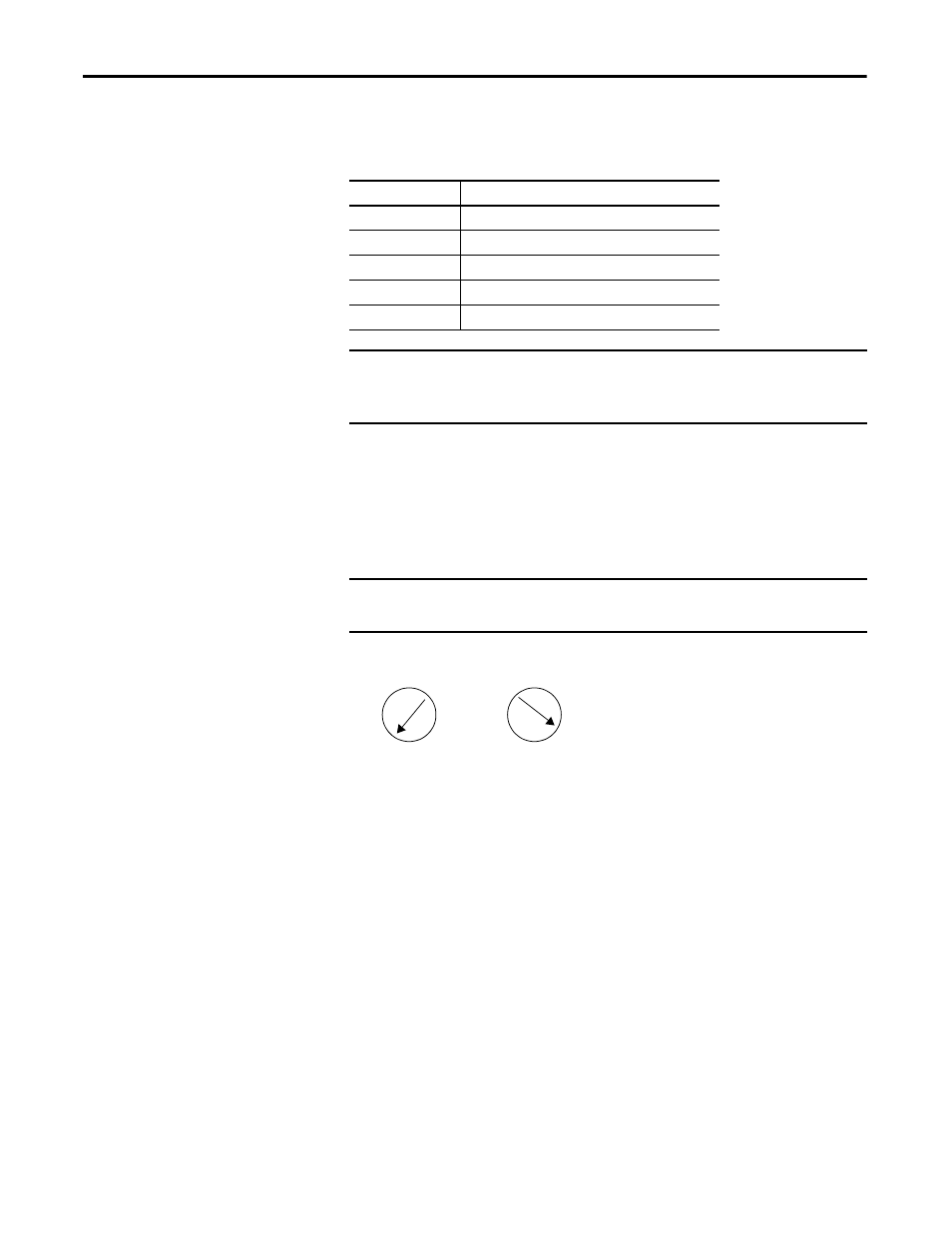
Figure 23 - Sample Node Address Digits
1. Set the node address by using the two rotary switches on the front panel of
the module, noting that the default setting is 63 and a value between
00…63 is valid for proper use.
2. Use the left rotary switch to set the tens digit of node address (decimal).
3. Use the right rotary switch to set the ones digit.
If the node address switches are set from 64…99, the node address needs to be set
from RSNetWorx for DeviceNet software.
Color
Signal
Red
Power cable positive side (V+)
White
High side of communication data (CAN_H)
-
Shield
Blue
Low side of communication data (CAN_L)
Black
Power cable negative side (V-)
IMPORTANT
When connecting a communication connector with the module,
tighten the screws on the communication connector to the specified
torque setting as shown in the installation instructions.
IMPORTANT
The node-address setting rotary switches must be set while the
communication power supply is turned off.
Tens Digit
Ones Digit
|
|
|
|
|
2
4
6
8
0
|
|
|
|
|
2
4
6
8
0
X1
X10