Rockwell Automation 1791DS-IBxxxx Guard I/O DeviceNet Safety Modules User Manual
Page 132
132
Rockwell Automation Publication 1791DS-UM001J-EN-P - May 2013
Chapter 8
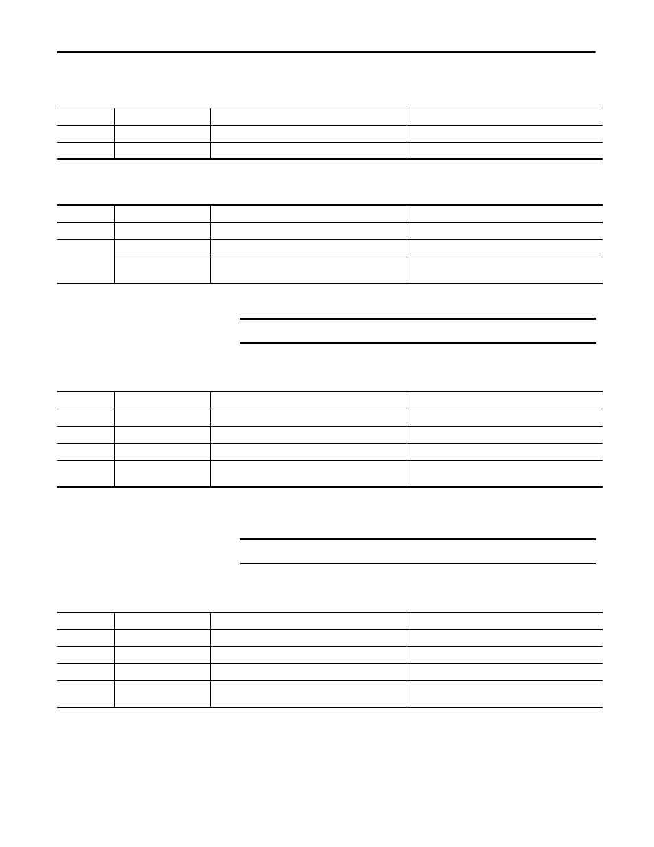
Interpret Status Indicators
Table 6 - Input Power (IN PWR) Indicator
State
Status
Description
Recommended Action
Solid green
Normal
Normal status of input power.
None.
Off
No input power
Input power is not supplied.
Apply input power.
Table 7 - Output Power (OUT PWR) Indicator
State
Status
Description
Recommended Action
Solid green
Normal
Normal status of output power.
None.
Off
No output power
Output power is not supplied.
Supply output power.
Output power exceeds power
range
Output power exceeds the upper/lower limit of power range.
Correct output power.
IMPORTANT
The I/O indicators are not lit while the module is being configured.
Table 8 - Input (IN0 through INn
(1)
) Indicators
State
Status
Description
Recommended Action
Solid yellow
On
Safety input is on.
None.
Off
Off
Safety input is off.
None.
Solid red
Fault
A fault occurred in an input circuit.
Check connected device and wiring.
Flashing red
Fault in other channel
When dual channels are set: a fault occurred in the other
channel.
Correct fault in other channel.
(1) Where ‘n’ indicates the input number.
IMPORTANT
The I/O indicators are not lit while the module is being configured.
Table 9 - Output (OUT0 through OUTn
(1)
) Indicators
State
Status
Description
Recommended Action
Solid yellow
On
Safety output is on.
None.
Off
Off
Safety output is off.
None.
Solid red
Fault
A fault occurred in an output circuit.
Check connected device and wiring.
Flashing red
Fault in other channel
When dual channels are set, a fault occurred in the other
channel.
Correct fault in other channel.
(1) Where ‘n’ indicates the output number.