Values and states of tags – Rockwell Automation 1791DS-IBxxxx Guard I/O DeviceNet Safety Modules User Manual
Page 70
70
Rockwell Automation Publication 1791DS-UM001J-EN-P - May 2013
Chapter 5
Configure Modules with the Logix Designer Application
Values and States of Tags
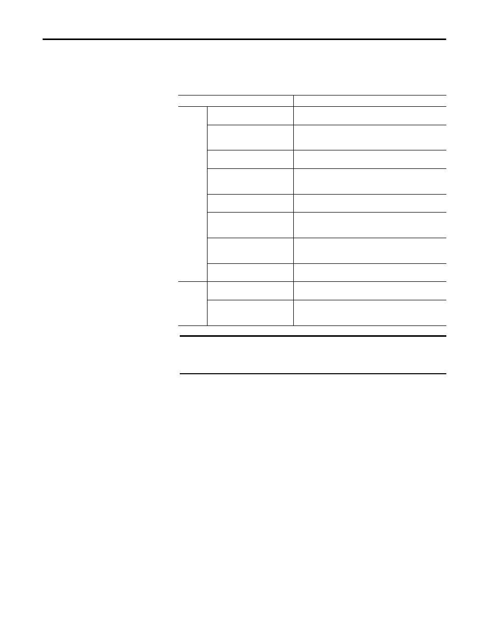
Use this table to determine the values and states of the tags.
Data
Description
Input data Safety Input Data
SAFETY
Indicates the ON/OFF status of each input circuit.
·ON: 1 OFF: 0
Combined Safety Input Status
SAFETY
An AND of the status of all input circuits.
·All circuits are normal: 1
·An error was detected in one or more input circuits: 0
Individual Safety Input Status
SAFETY
Indicates the status of each input circuit.
· Normal: 1 Fault (Alarm): 0
Combined Safety Output Status
SAFETY
An AND of the status of all safety output circuits.
·All circuits are normal: 1
·An error has been detected in one or more output circuits: 0
Individual Safety Output Status
SAFETY
Indicates the status of each safety output circuit.
·Normal: 1 Fault (Alarm): 0
Muting Lamp Status
SAFETY
Indicates the status when circuit T3, T7, T11, and T15 is configured
as the muting lamp output.
·Normal: 1 Fault (Alarm): 0
Output Readback
STANDARD
Monitors the presence of 24V on the output circuit. Readback is ON
(1) if 24V is on output terminal.
·ON: 1 OFF: 0
Individual Test Output Status
STANDARD
Indicates the status of each of the test output circuits.
·Normal:1 Fault (Alarm): 0
Output
data
Safety Output Data
SAFETY
Controls the safety output.
·ON: 1 OFF: 0
Standard Output Data
STANDARD
Controls the test output when Test Output mode is set to a standard
output.
·ON: 1 OFF: 0
IMPORTANT
Safety denotes information the controller can use in safety-related
functions. Standard denotes additional information that must not be relied
on for safety functions.