Rockwell Automation 193-EC4 EC4 Current Monitoring Relay User Manual User Manual
Page 61
62
Rockwell Automation Publication 193-UM011A-EN-P - September 2010
Chapter 5 Programmable Parameters
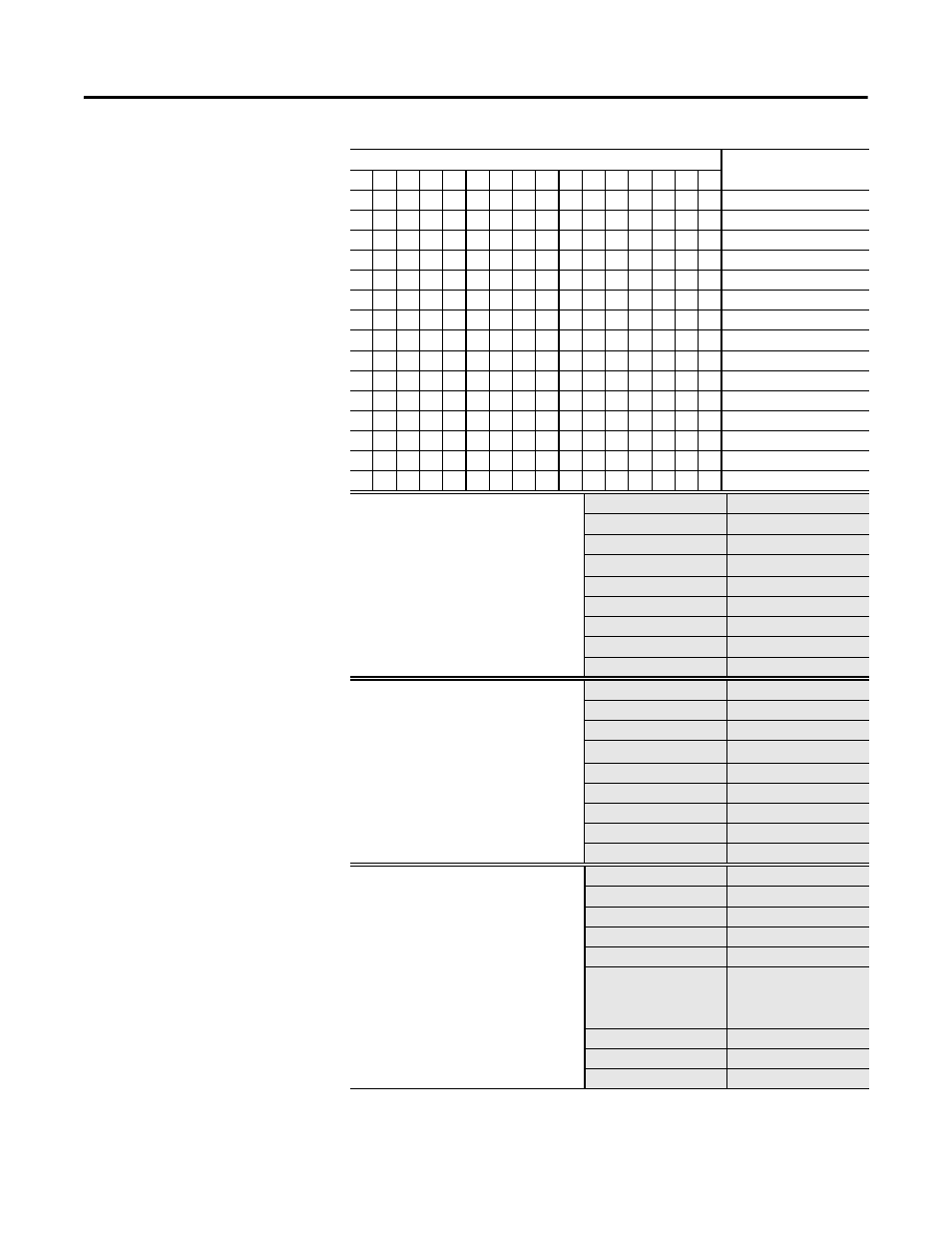
Bit
Function:
15 14 13 12 11 10 9
8
7
6
5
4
3
2
1
0
X
Ground Fault
X
L1 Undercurrent
X
L2 Undercurrent
X
L3 Undercurrent
X
L1 Overcurrent
X
L2 Overcurrent
X
L3 Overcurrent
X
L1 Loss
X
L2 Loss
X
L3 Loss
X
Comm Fault
X
Comm Idle
—
X
PM — #Starts
X
PM — Oper. Hours
GF INHIBIT TIME
This parameter defines the amount of time
for which ground fault detection is inhibited
during a motor starting sequence.
Parameter Number
35
Access Rule
Get/Set
Data Type
USINT
Object Mapping
2C
hex
-1-135
Group
Advanced Setup
Units
Seconds
Minimum Value
0
Maximum Value
250
Default Value
10
GF TRIP DELAY
This parameter allows the installer to
program a time duration for which a ground
fault condition must exist at the programmed
level prior to the device tripping.
Parameter Number
36
Access Rule
Get/Set
Data Type
USINT
Object Mapping
2C
hex
-1-136
Group
Advanced Setup
Units
Seconds
Minimum Value
0
Maximum Value
25.0
Default Value
0.5
GF Sensing Range
This parameter selects one of the
Ground Fault Sensing Ranges:
20…100 mA➊
100…500 mA
200 mA…1.0 A
1.0…5.0 A
➊For use with resistive loads only.
For motor loads, consult factory.
Parameter Number
106
Access Rule
Get/Set
Data Type
USINT
Object Mapping
2Chex-1-181
Group
Advanced Setup
Units
0 = 20…100 mA
1 = 100…500 mA
2 = 200 mA…1.0 A
3 = 1.0…5.0 A
Minimum Value
0
Maximum Value
3
Default Value
3