Devicenet troubleshooting procedures, Input and output troubleshooting procedures, Loss of node address – Rockwell Automation 193-EC4 EC4 Current Monitoring Relay User Manual User Manual
Page 115
116
Rockwell Automation Publication 193-UM011A-EN-P - September 2010
Chapter 11 Troubleshooting
DeviceNet Troubleshooting
Procedures
The following table identifies possible causes and corrective actions when
troubleshooting DeviceNet related failures using the
NETWORK STATUS
LED.
Loss of Node Address
Please refer to DeviceNet Node Commissioning on page 4-48 for further
information regarding node commissioning.
Input and Output
Troubleshooting
Procedures
Configuration
Fault
(warning)
1. Parameter 27, Single/Three Ph, is set to single phase and
current is being sensed in phase L3 during motor operation.
2. FLA setting is outside the “legal” range, as determined by the
corresponding CT Ratio setting.
1. For three-phase applications, Parameter 27, Single/Three Ph, should
be set to “three-phase”.
2. See Table 20 - and program the FLA setting within the range
specified.
Remote Trip
1. Contact closure of remote sensor (e.g., vibration switch).
1. Take corrective action to address the issue that caused the sensor to
actuate.
2. Check sensor for proper operation.
3. Check wiring.
PM - # Starts
(warning)
1. Parameter 96, Starts Counter, is equal to or greater than the
value set in parameter 101, PM - # Starts.
1. Set parameter 104, Clear Queue, to reset parameter 96, Starts
Counter.
PM – Oper.
Hours
(warning)
1. Parameter 95, Elapsed Time, is equal to or greater than the
value set in parameter 102, PM – Oper. Hours.
1. Set parameter 104, Clear Queue, to reset parameter 95, Elapsed
Time.
Table 24 - Trip/Warn LED Troubleshooting Procedures
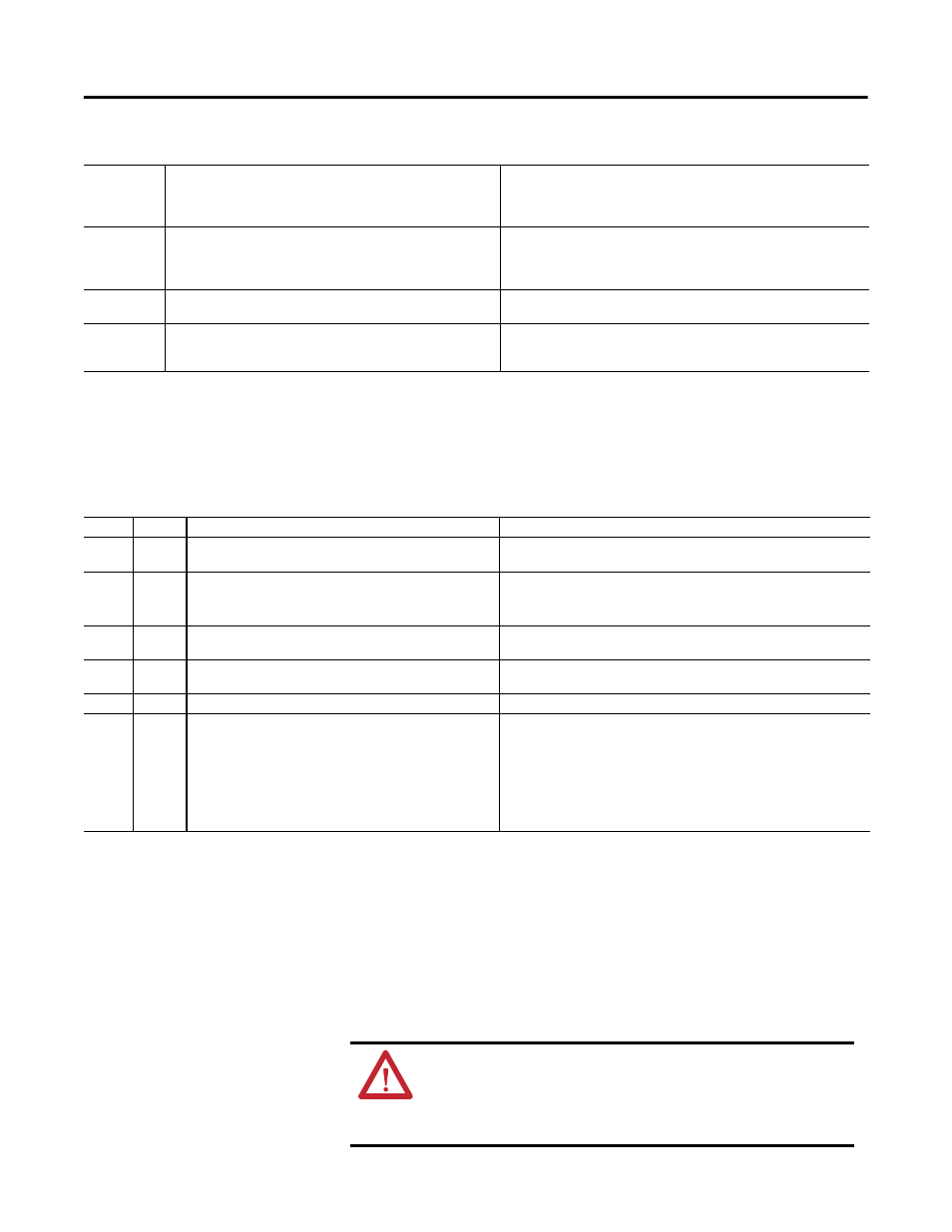
Table 25 - DeviceNet Troubleshooting Procedures
Color
State
Possible Cause
Corrective Action
None
1. The EC4 Current Monitoring Relay is not receiving power
at the DeviceNet connector.
1. Check DeviceNet power and cable connections and the power
connection on the DeviceNet connector.
Green
Red
Off
Flashing 1. The E3 or EC4 Current Monitoring Relay is trying to
determine the network baud rate
1. The current monitoring relay can not determine the network baud rate
if no network traffic exists. Network traffic can be induced by
invoking a Network Who using DeviceNet Manager.
Green
Flashing 1. Current Monitoring Relay is on-line but not allocated to a
master.
1. Check DeviceNet master and its scan list for correct scanner
configuration.
Green
Solid
1. Normal operating state, and the EC4 Current Monitoring
Relay is allocated to a master.
1. No action required.
Red
Flashing 1. I/O connection timed-out
1. Reset DeviceNet master device.
Red
Solid
1. Diagnostics test failed on power-up/reset. Internal fault
exists.
2. Duplicate DeviceNet node address exists (two DeviceNet
nodes cannot have the same address).
3. Invalid baud rate (if autobaud is disabled).
1. Cycle power to the unit and network. If the fault still exists, replace
unit.
2. Change the value of Parameter 57, NonVol MAC ID, to a valid address
and reset the device.
3. This will only occur if Parameter 55, AutoBaudEnable, is set to
“disabled”. Set Parameter 55 to “enabled” and reset the EC4 Current
Monitoring Relay (or) set Parameter 56, NonVol Baud Rate, to the
correct setting and reset the EC4 Current Monitoring Relay.
ATTENTION: If the outputs are to be commanded via an explicit
message, ensure that there can never be an established I/O
connection that can actively control them, and that the explicit
message connection has a non-zero expected packet rate (EPR)
setting.