External line current transformer application, Current transformer specifications – Rockwell Automation 193-EC4 EC4 Current Monitoring Relay User Manual User Manual
Page 27
28
Rockwell Automation Publication 193-UM011A-EN-P - September 2010
Chapter 2 Installation and Wiring
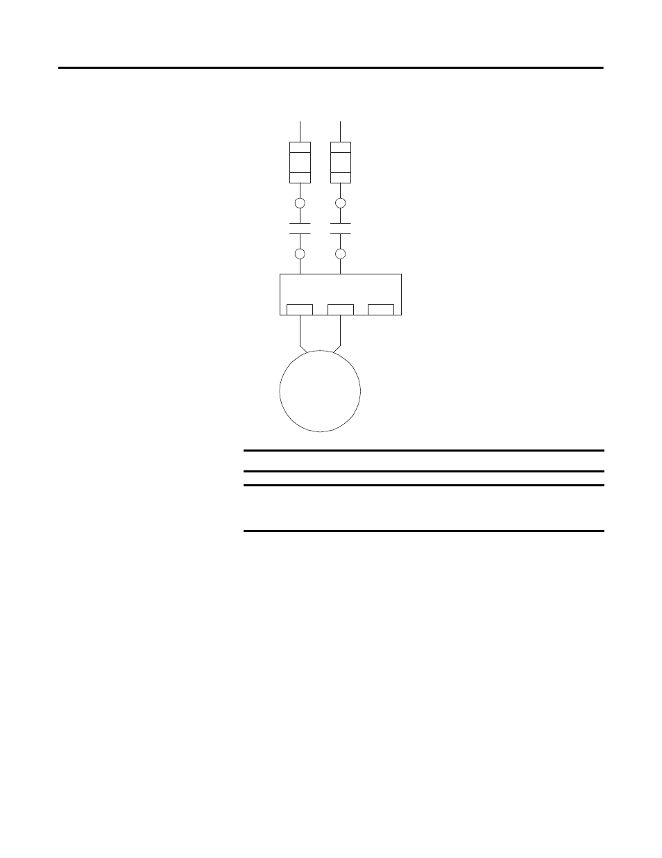
Figure 11 - Single-Phase Full-Voltage Wiring Diagram
External Line Current
Transformer Application
EC4 Current Monitoring Relays are designed for use with separately mounted,
customer-supplied line current transformers (CTs) as required in higher-current
applications. The FLA setting range is 9…5000 A for these units, with a legal
setting range per current transformer. Parameter 78,
CT Ratio, is provided for
setting the current transformer ratio to be installed.
Current Transformer Specifications
The 193-EC_ZZ current monitoring relays are intended for use with CTs with a
secondary current rating of 5 A. The installer shall provide one CT for each
motor phase and shall connect the CT’s secondary leads to the appropriate EC4
Current Monitoring Relay power terminals as shown in . The CTs shall have an
appropriate ratio rating as detailed in Table 3.1. Additionally, the CT shall be
selected to be capable of providing the required VA to the secondary load, which
includes the EC4 Current Monitoring Relay burden of 0.1 VA at the rated
IMPORTANT
Parameter 27, Single/Three Ph, should be set to single-phase.
IMPORTANT
Traditional single-phase wiring (connecting T2 to L3) will result in a
vector imbalance of current flowing through the EC4 Current Monitoring
Relay. This will result in inaccurate ground fault reporting and protection.
S.C.P.D.
E3 / E3 Plus
L 1
L 2
2/T1
4/T2
6/T3
M
T1
T2