Rockwell Automation 193-EC4 EC4 Current Monitoring Relay User Manual User Manual
Page 30
Rockwell Automation Publication 193-UM011A-EN-P - September 2010
31
Installation and Wiring Chapter 2
6.
The power system may be solidly grounded or grounded through an
impedance at its source as long as the impedance allows a magnitude of
current to flow that is within the 20 mA…5 A operational range of the
EC4 Current Monitoring Relay.
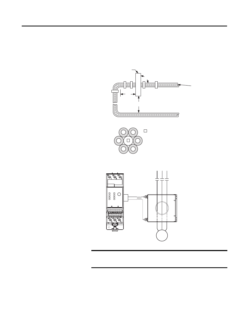
Figure 14 - Ground Fault Sensor Mounting Placement
Figure 15 - Power Cable Configuration — Two Cables per Phase
Figure 16 - Ground Fault Sensor Wiring to the EC4 Current Monitoring Relay
Maximum length of the shielded cable is 100 ft. All control terminals are for
copper wire only in sizes #12…24 AWG. Ring lug termination is required for the
ground sensor terminals of Cat. Nos. 193-CBCT2 and larger. Sensor fastener
torque: 26…30 lb-in. Cat. No. 193-CBCT1 wires should be twisted before
termination by applying one twist per inch.
IMPORTANT
The shield of the twisted pair cable must be connected to earth ground
at the sensor, with no connection made at the EC4 Current Monitoring
Relay.
Power
Cables
GF Sensor
6x
6x
90˚
L1
L2
L2
L3
L3
L1
1
1
The spacer is a short (approximately 10 times
the cable diameter in length) piece of cable
with no connections to any terminal.
Motor
L2 L
3
L1
S
1
S
2
E3 Plus Overload Relay
Cat. No. 193-CBCT_
Ground Fault Sensor