Rockwell Automation 21G PowerFlex 750-Series AC Drives User Manual
Page 276
276
Rockwell Automation Publication 750-IN001N-EN-P - April 2014
PowerFlex 750-Series AC Drives
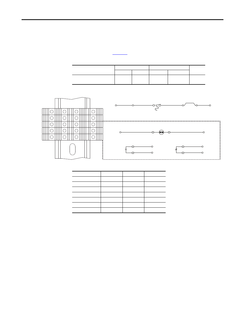
Control Wiring - Early Frame 8 Drives with Cabinet Options
Control terminal block TB2 is mounted on the inside right panel of the cabinet options bay
on early production frame 8 drives. TB1 referenced in the illustrations below resides on the
main control board. See
Table 97 - TB2 Terminal Block Specifications
Figure 140 - Control Terminal Block TB2 - Floor Mount Frame 8 Drives
Table 98 - Input/Output Contactor Data
Name
Wire Size Range
Torque
Strip
Length
Maximum
Minimum
Maximum
Recommended
Control Terminal Block TB2
4.0 mm
2
(12 AWG)
0.5 mm
2
(20 AWG)
0.5 N•m
(4.5 lb•in)
0.4 N•m
(3.5 lb•in)
8 mm
(0.32 in.)
6
7
8
9
10
6
7
8
9
10
1
2
3
4
5
1
2
3
4
5
Input/Output Contactor
M2/M4
TB2(8)
TS1
Thermostat
TB2
W1
Hardware Enable Jumper
Note: Remove W1 jumper to
connect a hardware enable circuit.
TB2(7)
TB2(6)
TB1(Di 0dc)
TB2(1)
TB1(+24V)
A1
A2
13
14
TB2(9)
TB2(4)
M2/M4
21
22
TB2(5)
TB2(10)
M2/M4
TB2(3)
Optional Devices
Cat. No.
(1)
(1) For full contactor specifications refer to publications 100D-SG001 and 100G-SG001.
Input
Pick-Up
Hold-In
100-D420EA11
50 Hz
490VA
18VA
100-D420ED11
60 Hz
490VA
18VA
100-D630EA11
50 Hz
1915VA
33VA
100-D630ED11
60 Hz
1915VA
33VA
100-D860EA11
50 Hz
1915VA
33VA
100-D860ED11
60 Hz
1915VA
33VA
100-G1200KD12
60 Hz
2,400VA
70VA