Rockwell Automation 21G PowerFlex 750-Series AC Drives User Manual
Page 168
168
Rockwell Automation Publication 750-IN001N-EN-P - April 2014
PowerFlex 750-Series AC Drives
690V A
C Inp
u
t (cont
inued)
932V
DC
Inp
ut
(cont
inu
ed
)
80
0 kW
9
795
Hea
vy
20G
…F960
119
3
1440
74
9
90
0
100
0
950
47
5
1700
95
0
475
22
00
2200
95
0
875
100
0
795
Norm
al
20G
…F795
875
1350
74
9
90
0
100
0
950
47
5
1700
950
475
22
00
2200
950
875
100
0
790
Li
gh
t
20G
…F710
869
–
74
4
90
0
100
0
950
47
5
1700
95
0
475
22
00
2200
95
0
869
100
0
85
0 kW
9
860
Li
ght
20G
…F765
946
–
81
0
90
0
100
0
100
0
50
0
1800
1000
500
24
00
2400
1000
946
100
0
90
0 kW
9
960
No
rm
al
20G
…F960
105
6
1440
90
4
90
0
100
0
115
0
57
5
2000
1150
575
27
00
2700
1150
1056
100
0
960
Li
ght
20G
…F795
105
6
–
90
4
90
0
100
0
115
0
57
5
2000
1150
575
27
00
2700
1150
1056
100
0
10
865
Hea
vy
20G
…F1K0
129
8
1560
81
5
90
0
100
0
100
0
50
0
1800
1000
500
24
00
2400
1000
952
100
0
10
00 kW
9
102
0
Li
ght
20G
…F795
112
2
–
90
4
90
0
100
0
120
0
60
0
2200
1200
600
29
00
2900
1200
1056
100
0
10
104
0
No
rm
al
20G
…F1K0
114
4
1560
98
0
90
0
100
0
125
0
62
5
2200
1250
625
29
00
2900
1250
1144
100
0
11
00 kW
10
115
0
Li
ght
20G
…F1K0
126
5
1380
10
83
90
0
100
0
135
0
67
5
2400
1350
675
32
00
3200
1350
1265
100
0
11
20 kW
10
116
0
Hea
vy
20G
…F1K4
174
0
2100
10
93
90
0
100
0
135
0
67
5
2500
1350
675
33
00
3300
1350
1276
100
0
14
00 kW
10
140
0
N
orm
al
20G
…F1K4
154
0
2100
13
19
90
0
100
0
165
0
82
5
3000
1650
825
40
00
4000
1650
1540
100
0
15
00 kW
10
148
5
Li
gh
t
20G
…F1K4
163
4
1782
13
99
90
0
100
0
175
0
87
5
3100
1750
875
42
00
4200
1750
1634
100
0
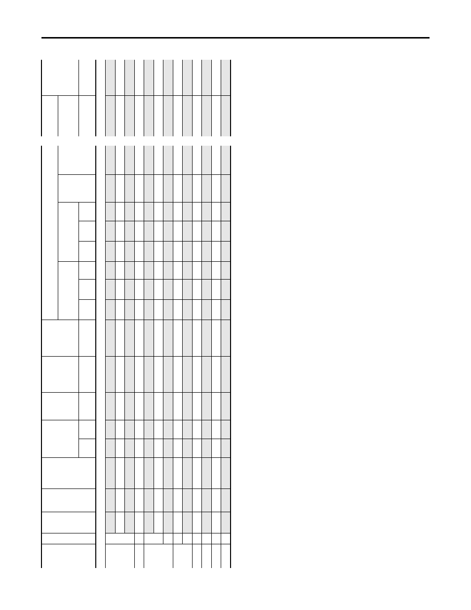
(1)
“Ap
pl
ie
d R
ating
” r
efe
rs
to
the m
ot
or tha
t w
ill
b
e connec
te
d t
o the d
riv
e.
F
or exa
m
pl
e,
a
“F400”
driv
e c
an
be us
ed
in Norma
l D
ut
y
m
od
e o
n a
4
00
k
W
m
ot
or
, i
n H
eav
y D
ut
y m
od
e o
n a
3
55
k
W
m
ot
or
o
r i
n L
ig
ht
D
ut
y m
od
e o
n a
4
50
k
W
m
ot
or
. T
he
d
riv
e c
an
b
e p
ro
gramme
d
for each mod
e.
W
iring
and fuses can be siz
ed based
on th
e pr
ogra
mme
d mod
e.
Fo
r an
y giv
en driv
e c
atalog number
, N
or
m
al D
ut
y mod
e pr
ov
ides higher con
tinuous c
urr
en
t b
ut
smaller o
ver
load cu
rr
en
t with r
espec
t t
o Hea
vy D
ut
y mode
. S
ee
pa
ra
met
er 30
6 [D
ut
y
Ra
ting]. R
ef
er t
o Spec
ific
at
ions
fo
r an e
xpl
ana
tio
n
of Duty Ra
tings
.
(2
)
Thes
e A
C li
ne f
use
s (w
ith bl
ow
n f
use
indi
ca
to
rs)
ar
e
inc
lude
d in the
driv
e t
o
pr
ov
ide
driv
e s
hor
t ci
rc
uit pr
ot
ec
tion. A
C i
np
ut pr
ot
ec
tion dev
ic
es for branch c
irc
uit pr
ot
ec
tion based
on U
S
NE
C ar
e list
ed in
the
table
. E
ach driv
e ba
y has one f
use p
er ph
as
e.
(3)
M
inimum pr
ot
ec
tion devic
e siz
e is th
e l
ow
est ra
ted d
evi
ce
that sup
pl
ie
s m
ax
imum p
rot
ec
tion without nuisance trip
ping
.
(4)
M
aximum pr
ot
ec
tion devic
e siz
e is the hi
ghest r
at
ed devic
e tha
t sup
plies
driv
e pr
ot
ec
tion
. F
or U
S N
EC
, mi
nim
um si
ze
is
12
5%
of
motor FL
A. R
ating
s shown are ma
xi
mum
.
(5)
Circui
t B
rea
ke
r -
in
ve
rse
ti
m
e br
ea
ke
r. F
or U
S NEC, m
ini
mu
m s
iz
e is
1
25%
of
motor FL
A. R
ating
s s
hown are m
axi
m
um.
(6)
Rec
ommended Mot
or cir
cuit p
rot
ec
tor - Instan
taneous trip cir
cuit br
eak
er
. T
he trip setting
sh
ould
be set t
o the in
put curr
en
t of
the
driv
e and should be sized for the con
tinuo
us c
urr
ent
of
the syst
em
.
(7
)
Thes
e DC
li
ne f
use
s (w
ith bl
ow
n f
use
indi
ca
to
rs)
ar
e
inc
lude
d in the
driv
e t
o
pr
ov
ide
driv
e s
hor
t ci
rc
uit pr
ot
ec
tion.
Ap
pli
ed
Ra
ting
(1
)
Frame
Cont
.
Ou
tp
u
t
Amps
D
u
ty
Ca
ta
lo
g
Num
b
er
Ou
tp
u
t
O
ver
load Amps
Cont
inuous
AC
In
pu
t
AC
In
pu
t
Integra
l
Se
m
ic
on
d
u
ct
or
Fu
se
S
ize
(170M)
(2
)
DC Ba
y to B
ay
Int
egral
Semi
co
ndu
ct
or
Fu
se
S
ize
(170
M664
8)
AC
Inpu
t Pr
ot
ec
ti
on D
evi
ce
s R
eco
mme
nded
fo
r Br
an
ch C
ir
cu
it Pr
ot
ec
ti
on
(D
oe
s not
app
ly
to
2
1G
Dr
iv
es
wi
th Opt
ions)
Inp
u
t Q
u
an
tit
ies
DC
Inp
u
t
Inte
gral
Se
m
ic
on
d
u
ct
or
Fu
se
S
ize
(170M
6253)
(7
)
D
ual E
lem
ent
Tim
e Dela
y
Fu
se
Non-
Time Dela
y F
u
se
Ci
rc
ui
t
Br
ea
ke
r
Ma
x Si
ze
(5
)
Mot
or
Ci
rc
ui
t
Protec
tor
(6
)
Co
ntinuo
us D
C
Input
1 mi
n
3 s
ec
Amps
Am
ps
Amps
1/P
has
e
Mi
n
(3)
2/
Phas
e
Min
(3)
Max
(4)
1/
Ph
as
e
Mi
n
(3)
2/
Phas
e
Min
(3)
Ma
x
(4)
Am
ps
Am
ps