Hardware enable circuitry – Rockwell Automation 21G PowerFlex 750-Series AC Drives User Manual
Page 214
214
Rockwell Automation Publication 750-IN001N-EN-P - April 2014
PowerFlex 750-Series AC Drives
Hardware Enable Circuitry
Each main control board has one digital input, Digital Input 0, that can be used
as a general purpose programmable input, or by removal of a jumper, configured
as a dedicated hardware enable, which is unaffected by parameter settings.
•
PowerFlex 753 - Digital Input 0 is found on TB3
•
PowerFlex 755 - Digital Input 0 is found on TB1
To configure Digital Input 0 as a dedicated hardware enable, complete the
following steps.
1.
Access the control pod as described beginning on
2.
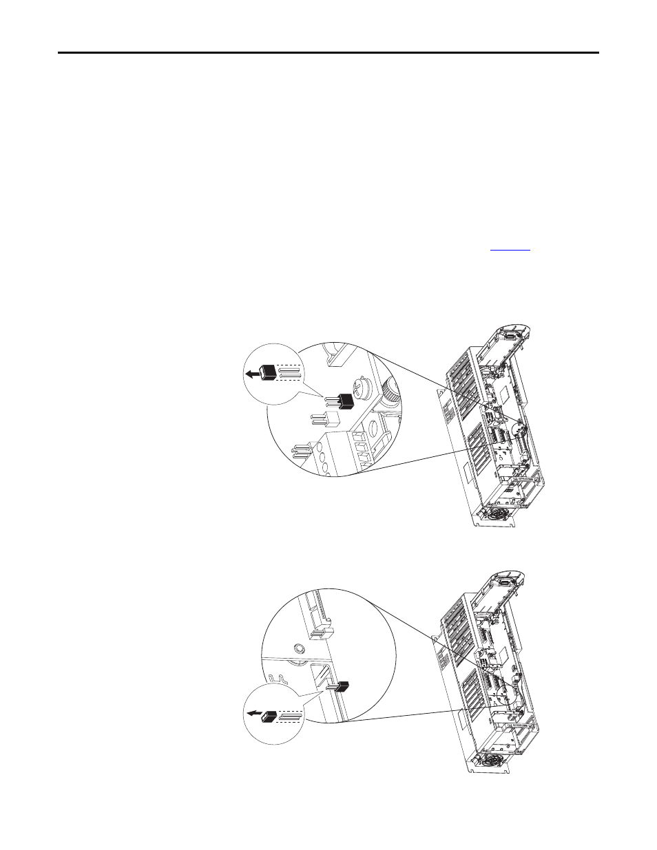
Locate and remove ENABLE Jumper on the Main Control Board (see
diagram).
PowerFlex 753 - ENABLE Jumper Location
PowerFlex 755 - ENABLE Jumper Location (Wall Mount Frames 1…7)