Rockwell Automation 21G PowerFlex 750-Series AC Drives User Manual
Page 205
Rockwell Automation Publication 750-IN001N-EN-P - April 2014
205
PowerFlex 750-Series AC Drives
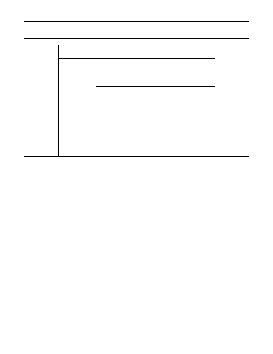
Table 35 - I/O Wire Recommendations
Type
Wire Type(s)
Description
Min. Insulation Rating
Signal
(1) (2) (3)
Standard Analog I/O
–
0.750 mm
2
(18AWG), twisted pair, 100% shield with drain. 300V,
75…90 °C
(167…194 °F)
Remote Pot
–
0.750 mm
2
(18AWG), 3 conductor, shielded.
Encoder/
Pulse I/O
<30 m (100 ft)
Combined
0.196 mm
2
(24AWG)
individually shielded pairs.
Encoder/
Pulse I/O
30 to 152 m
(100 to 500 ft)
Signal
0.196 mm
2
(24AWG)
individually shielded pairs.
Power
0.750 mm
2
(18AWG) in.dividually shielded pairs
Combined
0.330 mm
2
(22AWG), power is 0.500 mm
2
(20AWG)
individually shielded pairs.
Encoder/
Pulse I/O
152 to 259 m
(500 to 850 ft.)
Signal
0.196 mm
2
(24AWG)
individually shielded pairs.
Power
0.750 mm
2
(18AWG) individually shielded pairs.
Combined
0.750 mm
2
(18AWG) individually shielded pairs.
Digital I/O
Safety Inputs
Homing Inputs
(1)(2)(3)(4)
Shielded
Multi-conductor shielded cable
0.750 mm
2
(18AWG), 3 conductor, shielded.
300V,
60 °C
(140 °F)
Digital I/O
Homing Inputs
(1)(2)(3)
Un-shielded
–
Per US NEC or applicable national or local code.
(1) Control and signal wires should be separated from power wires by at least 0.3 meters (1 foot).
(2) If the wires are short and contained within a cabinet which has no sensitive circuits, the use of shielded wire may not be necessary, but is always recommended.
(3) I/O terminals labeled “(–)” or “Common” are not referenced to earth ground and are designed to greatly reduce common mode interference. Grounding these terminals can cause signal noise.
(4) Safety option modules 20-750-S and 20-750-S1 require shielded cable.