Infrared co, Sensor, Infrared sub pcb – RKI Instruments EAGLE 2 Manual User Manual
Page 234
224 • Description
EAGLE 2 Operator’s Manual
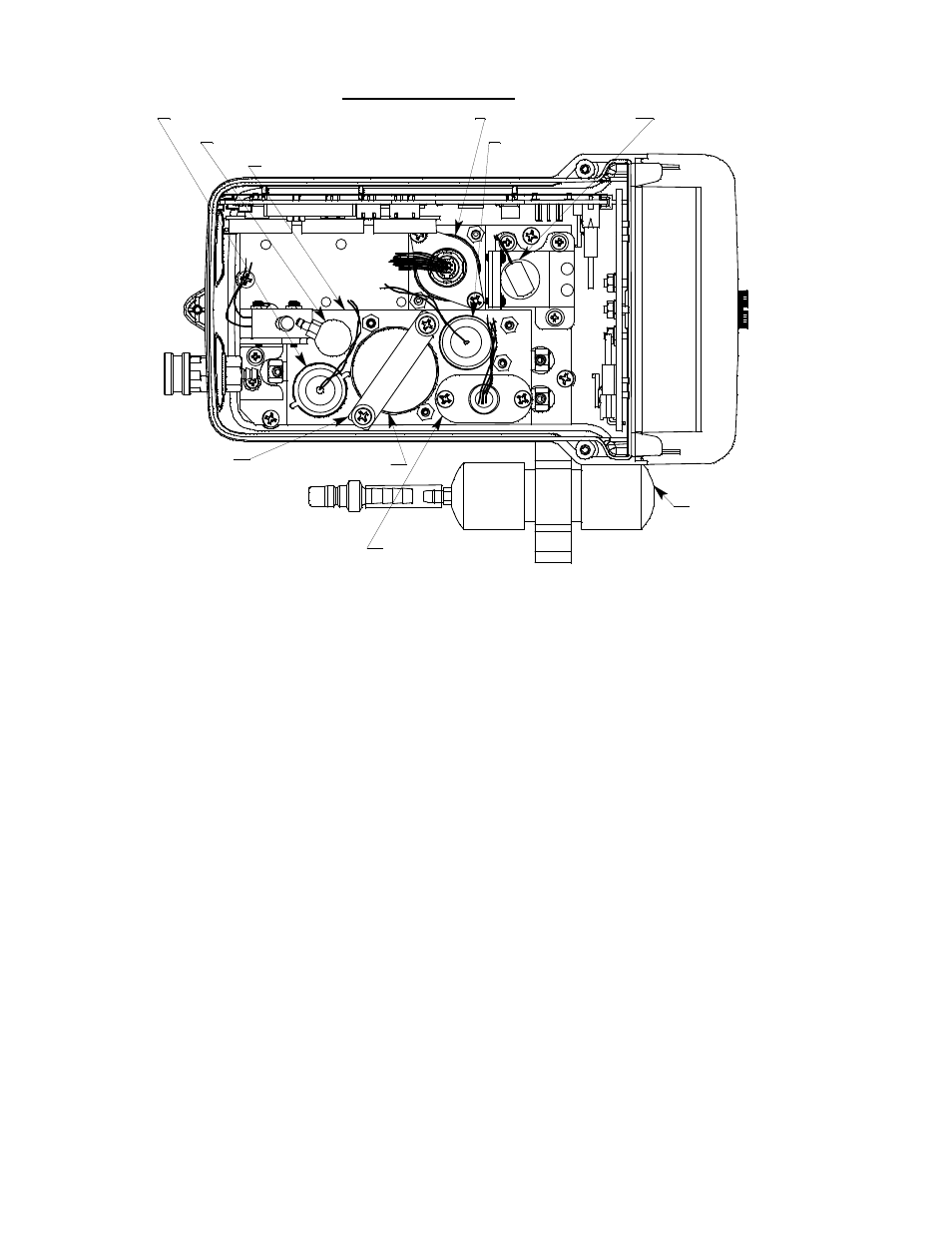
Figure 38: Typical Infrared CO
2
Sensor Location
The infrared CO
2
sensor is installed in a single sensor flow chamber which is
located in the area next to the standard 4-sensor flow chamber. This area can
accommodate up to three single sensor flow chambers. Figure 38 above
illustrates a typical infrared CO
2
sensor location in front of the pump. The
infrared CO
2
flow chamber may also be installed in one of the other two
sensor chamber locations depending on the particular version of the EAGLE
2. Some infrared CO
2
instrument configurations do not include the 4-sensor
flow chamber.
Infrared CO
2
Sensor
The infrared CO
2
sensor is a cylindrical sensor with a diffusion opening on
the front and a 12 pin circular connector on the back. A 12 wire cable plugs
into the back of the infrared CO
2
sensor with a circular connector that
includes a locking lever. The other end of the cable plugs into an infrared sub
PCB (see description below) that is installed on the main PCB. The sensor is
held in the infrared flow chamber by a bracket on standoffs.
Infrared Sub PCB
The infrared sub PCB is a circuit board that is installed on the main PCB in
H2S Sensor
Pump
Top Case Not Shown
CO2 Scrubber
Infrared CO2 Sensor
Standard Flow Chamber
Charcoal Filter
CO Sensor
Oxygen
Sensor
Bracket
LEL Sensor and
Sensor Bracket
Oxygen Sensor