Appendix c: sub pcbs overview, Description – RKI Instruments EAGLE 2 Manual User Manual
Page 142
132 • Overview
EAGLE 2 Operator’s Manual
Appendix C: Sub PCBs
Overview
An EAGLE 2 that has one or more of the standard four sensors, catalytic
LEL, oxygen, H
2
S, and CO, and no optional sensors does not have any sub
PCBs installed. The sub PCBs are used to add circuitry to the EAGLE 2 that
supports various optional sensors. An EAGLE 2 has provisions to install up
to three sub PCBs. Although an EAGLE 2 with three sub PCBs installed can
theoretically support seven sensors if you include the standard four sensors,
the EAGLE 2 is only capable of having six active channels.
Description
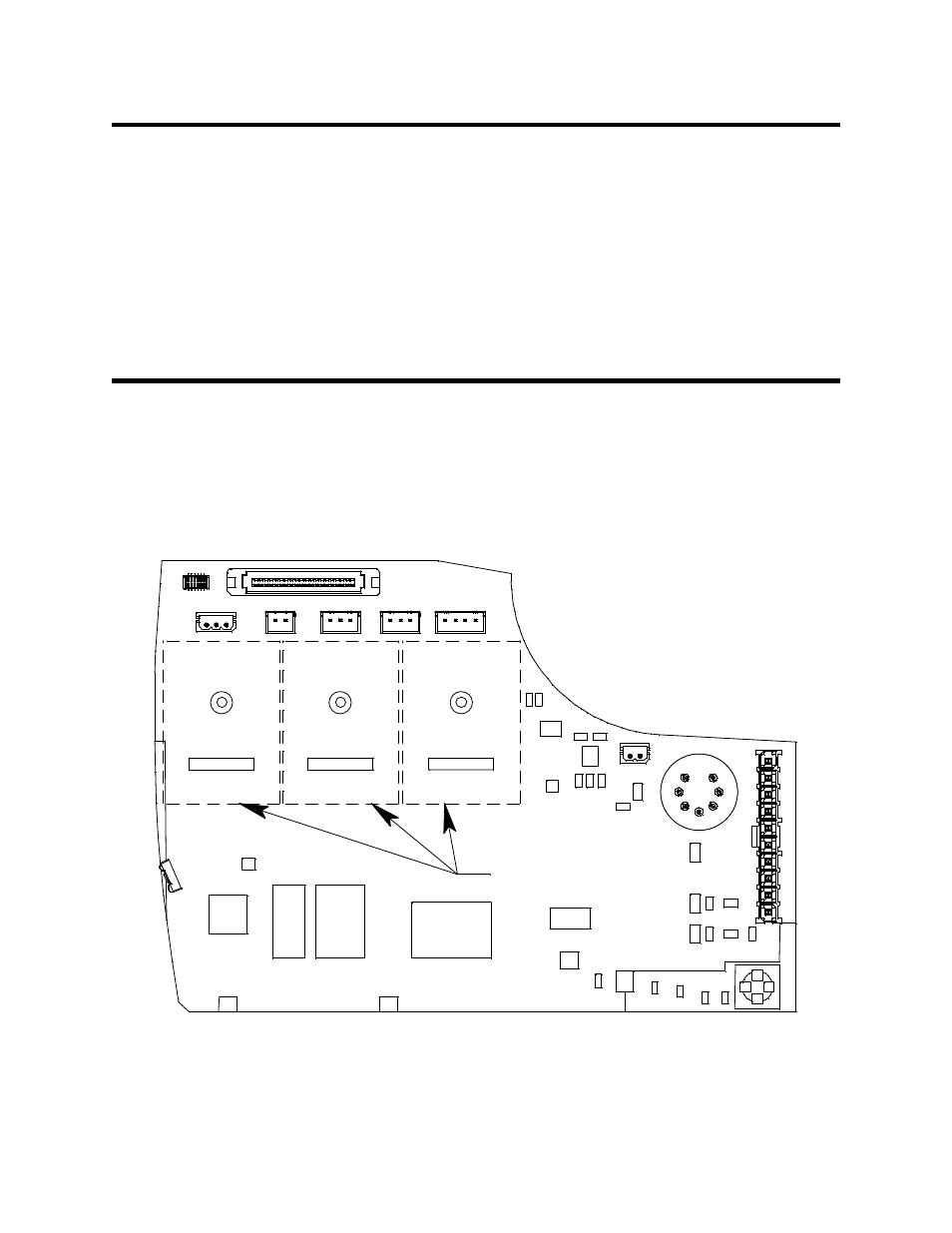
The main PCB can accept up to three sub PCBs. The sub PCBs are installed
below a row of connectors near the top of the main PCB. The three positions
are labeled on the main PCB silkscreen from right to left as SUB1, SUB2,
and SUB3. These labels are not visible when the sub PCBs are installed.
Figure 24: Sub PCB Positions
The sub PCBs plug into the main PCB with a multiposition connector and are
SUB2
SUB1
SUB3
Sub PCB Positions