RKI Instruments EAGLE 2 Manual User Manual
Page 215
EAGLE 2 Operator’s Manual
Description • 205
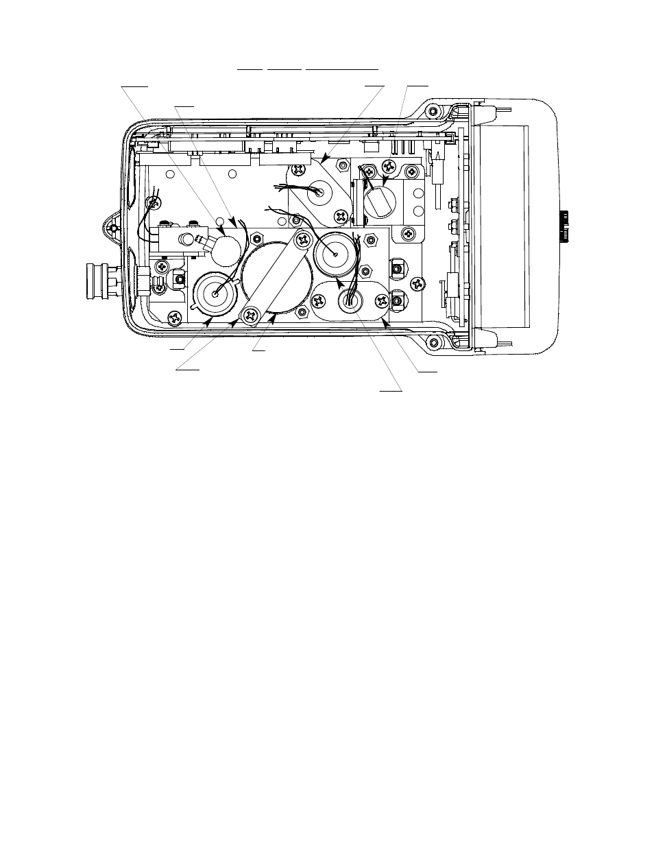
Figure 37: Typical TC Sensor Location
TC Sensor
The TC sensor’s appearance is exactly the same as that of the LEL sensor. Its
housing includes a sintered metal flame arrestor on one end that allows gas to
diffuse into the sensor. On the other end, five pins extend from the sensor.
The TC sensor can be distinguished from the LEL sensor by the part number
imprinted on it. The TC sensor part number is TE-7568 while the LEL part
number is NC-6260B. The sensor cable connects to pins on one end and
terminates in a four-position connector on the other end which plugs into the
TC sub PCB (see description below). The sensor bracket is installed over the
TC sensor to keep it seated in place.
NOTE: The LEL and TC sensors and sensor cables are identical in
appearance. Take care not to plug the LEL sensor cable into the port
on the TC sub PCB and not to plug the TC sensor cable into the LEL
port on the main PCB.
TC Sub PCB
The TC sub PCB is a circuit board that is installed on the main PCB in one of
the 3 sub PCB positions when a TC sensor is used with the EAGLE 2. The
CO Sensor
Pump
LEL Sensor and
Sensor Bracket
Charcoal Filter
Oxygen Sensor
Bracket
Standard Flow Chamber
Top Case Not Shown
TC Sensor
H2S Sensor
Oxygen Sensor