RKI Instruments EAGLE 2 Manual User Manual
Page 147
EAGLE 2 Operator’s Manual
Description • 137
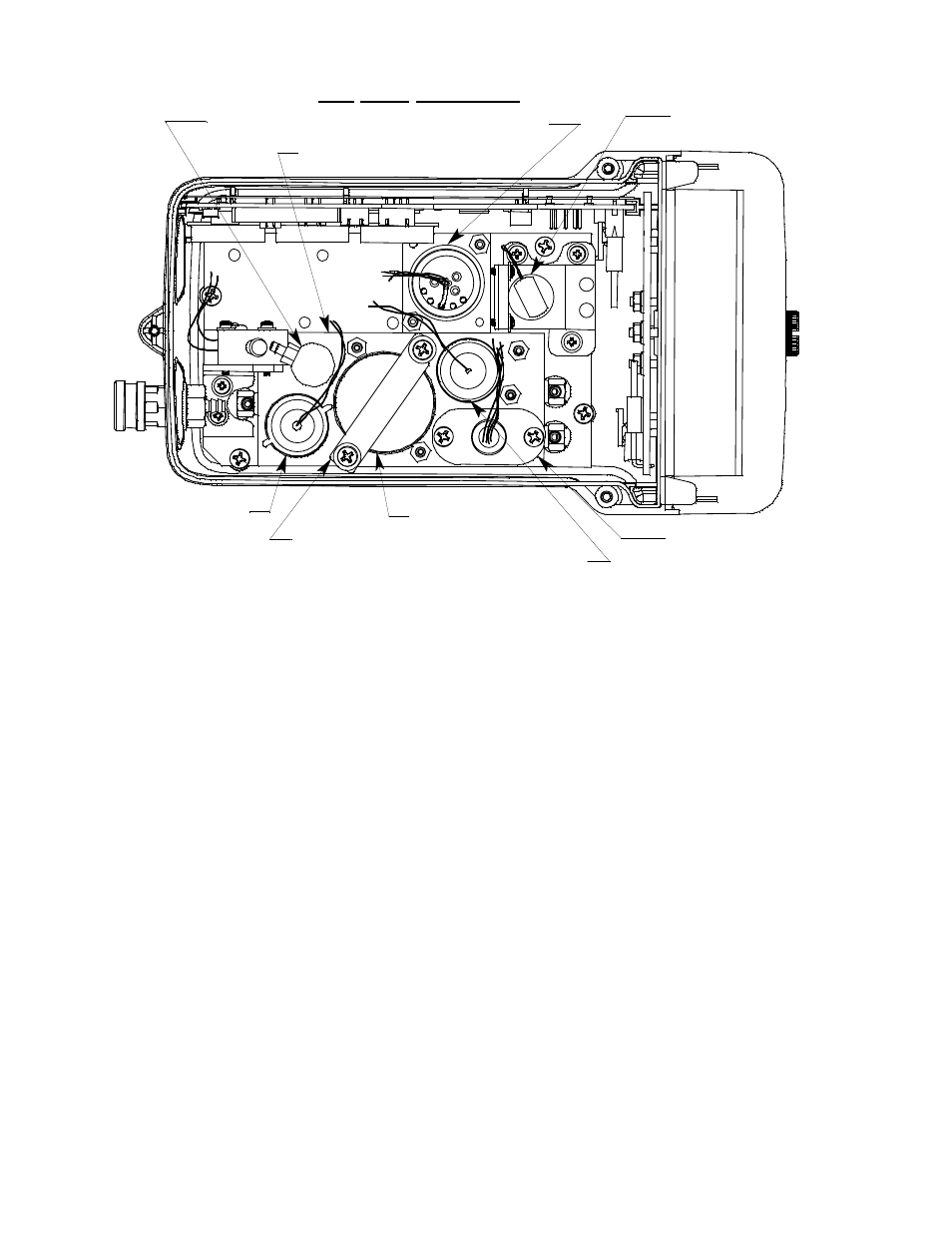
Figure 25: Typical PID Sensor Location
PID Sensor & Sensor Adapter
The PID sensor is a cylindrical sensor with a diffusion opening on the front
and 3 pins on the back. It is plugged into a sensor adapter with a 5 wire cable
that terminates in a 5-position connector. The connector plugs into a PID sub
PCB (see description below) that is installed on the main PCB. The sensor
adapter allows installation of the PID sensor into the PID flow chamber. The
sensor adapter is held in the PID flow chamber with two O-rings which also
seal around the sensor adapter.
PID Sub PCB
The PID sub PCB is a circuit board that is installed on the main PCB in one
of the 3 sub PCB positions when a PID sensor is used with the EAGLE 2.
The PID sensor adapter connects to the sub PCB with a 5-position connector.
The sub PCB plugs into the main PCB and is held in place with a screw/flat
washer/lock washer. There are no user serviceable parts on the PID sub PCB.
PID Probe
Several of the gases that can be monitored with a PID are easily absorbed in
the EAGLE 2’s standard sample hose and standard probe. One example of
this is styrene. Because of this, RKI Instruments, Inc. recommends that you
Pump
LEL Sensor and
Sensor Bracket
CO Sensor
Charcoal Filter
Oxygen Sensor
Bracket
Standard Flow Chamber
Top Case Not Shown
H2S Sensor
PID Sensor
Oxygen Sensor