RKI Instruments EAGLE 2 Manual User Manual
Page 144
134 • Channel Setup & Sub PCBs
EAGLE 2 Operator’s Manual
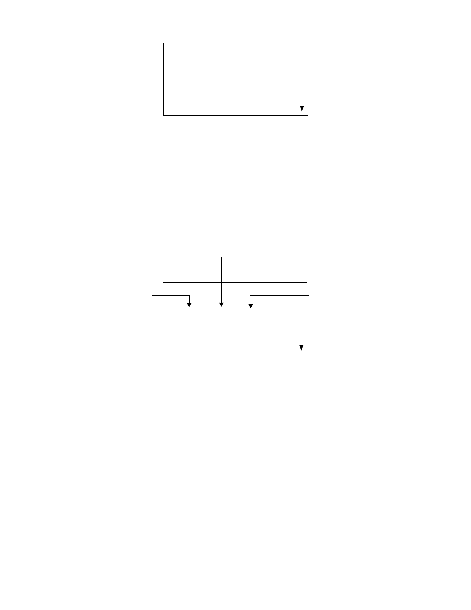
CONFIGURE CHANNELS LCD screen below illustrates this situation.
The “---” to the right of OP1 indicates that no sub PCB is installed in position
SUB1. See “Configuring the Channels” on page 105 for a complete
description of the CONFIGURE CHANNELS Setup Mode menu item.
Sub PCBs and CONFIGURE GASES
The CONFIGURE GASES menu item in Setup Mode allows you to
configure the gas for a catalytic, TC, or PID sensor that is installed. There are
four possible sensors that can be configured depending on the particular
version of the EAGLE 2. The LCD screen below illustrates the first screen in
the CONFIGURE GASES menu item in Setup Mode.
The four possible sensors are a catalytic sensor and three optional sensors.
They are listed with the following information from left to right:
•
The circuitry that supports the sensor and whether it is standard or
optional
This can be the catalytic circuit on the main PCB indicated by CAT or
one of the sub PCBs indicated by OP1 (option 1), OP2 (option 2), and
OP3 (option 3). OP1 indicates that the SUB1 PCB supports the
sensor, OP2 indicates that the SUB2 PCB supports the sensor, and
OP3 indicates that the SUB3 PCB supports the sensor. The OP1,
OP2, and OP3 identifiers also indicate that the sensor is an optional
sensor. The catalytic sensor is a standard sensor. Each of these is
always listed.
CONFIGURE CHANNELS
> CH1: CAT (CH4)
CH2: OXY (OXY)
CH3: H2S (H2S)
CH4: OP1 (---)
CONFIGURE GASES
> CAT : CH4 (CAT)
OP1 : IBL (PID)
OP2 : NH3 (ESM)
OP3 : --- (---)
Supporting Circuitry/
Currently Configured
Sensor Type
Gas
Std. or Optional