Programming the bolt circle, 1 demonstr ation pr ogr am – ACU-RITE MILLPWRG2 User Manual
Page 139
ACU-RITE MILLPWR
G2
121
7.
1 Demonstr
ation Pr
ogr
am
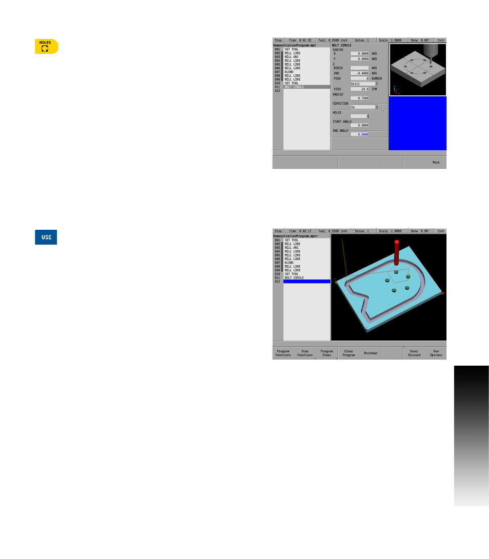
Programming the Bolt circle
Press the HOLES key.
A popup menu will appear for selecting the type of hole pattern to be
used.
Select the Bolt Circle selection. The BOLT CIRCLE input dialogue
will be displayed.
In the CENTER X field enter 0.00, and Y field enter 0.00. For this
program it is also the CENTER location for the Bolt Circle (which is
also where datum X 0 and Y0 was set).
ARROW
down to highlight the Z: END field, and press the CLEAR key to
delete the default data in the field that may be present.
Enter a value of -.40 in the Z: END field.
ARROW
down to highlight the PECK field, and enter 6 for the
NUMBER.
ARROW
down to highlight the RADIUS field. Press the CLEAR key to
delete any default data in the field, then enter 0.75.
ARROW
down to highlight the DIRECTION field, and press the CW
(Clockwise) soft key.
ARROW
down to highlight the HOLES field, and enter 5.
Press the USE key.
In this example, the starting and ending angles were not changed. As
a result, the first hole is placed at zero degrees. If you were to look at
the face of a clock, zero degrees will be at 3 o’clock. Without a
specified ending angle MILLPWR
G2
spaces the number of holes
entered evenly around a full circle. If a counter-clockwise direction
was applied to the hole pattern, the second hole of our five hole
pattern will be between 12 o’clock and 1 o’clock. The holes continue
around the circle as shown below.